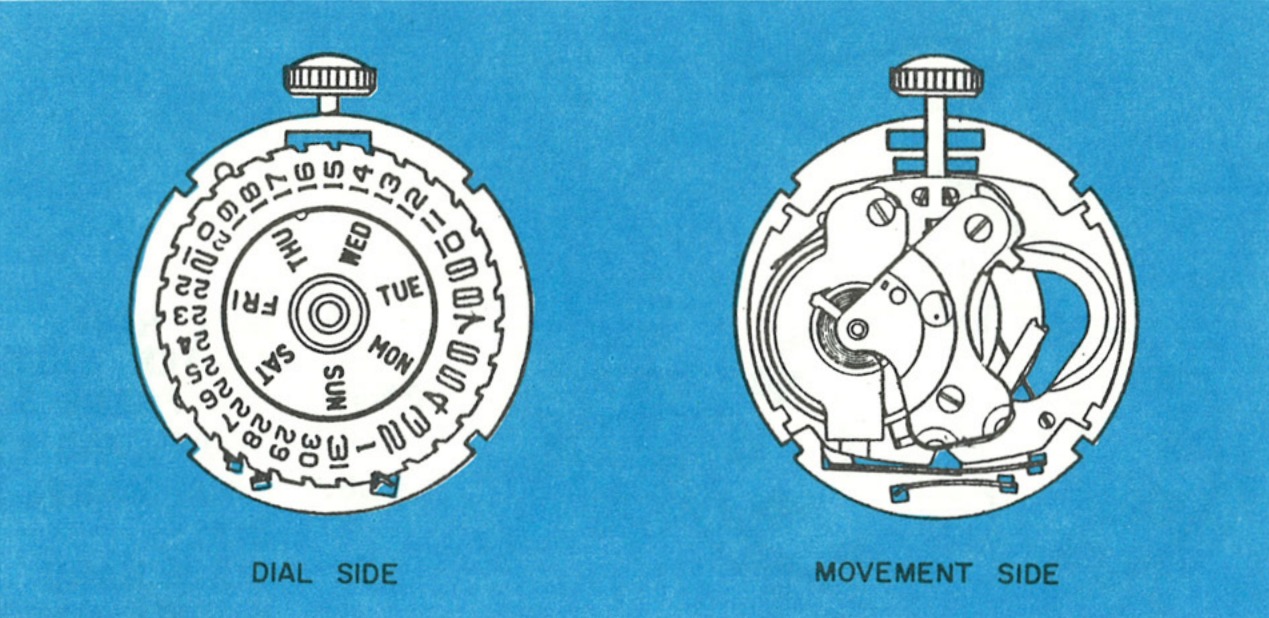
An electronic day-date movement on Model 50 principles. The day and the date are set by two different motions of the crown, and the date will only go forwards.
The Timex Model 52 is a 13½ ligne electronic day-date movement. The Model 52 movement is similar to the Model 50 movement except that a calendar and a day mechanism have been added. Power from a miniature energy cell drives the balance, and the balance drives the time train which, in turn, rotates the hands.
Setting the day: Pull the crown out to the set position and turn through 24 hours in either direction.
Setting the date: Push the crown into the run position and turn it counterclockwise. The date increases one number for each half turn. Do NOT turn the crown clockwise when in the run position.
Basic servicing techniques are similar to those used for the Model 50, except that all hands must be removed prior to removing the dial. For the electronic movement itself, see the Model 50 guide. The day-date work is the same as the electric Model 42.
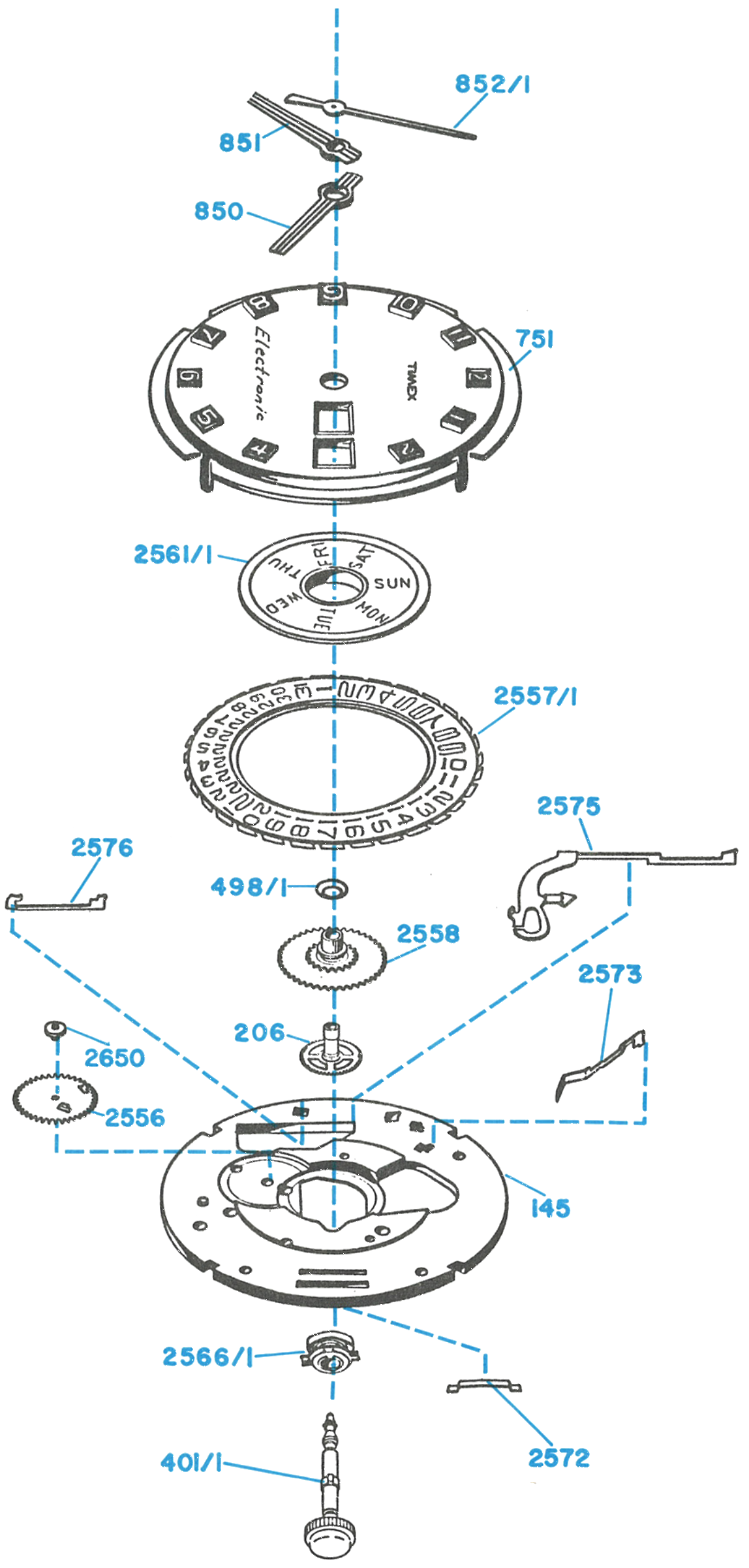
Exploded View
Everything below the numbered parts is the Model 50 electronic movement.
Remove, in order as described for the Model 50, the caseback, energy cell, movement cover, and crown and stem assembly.
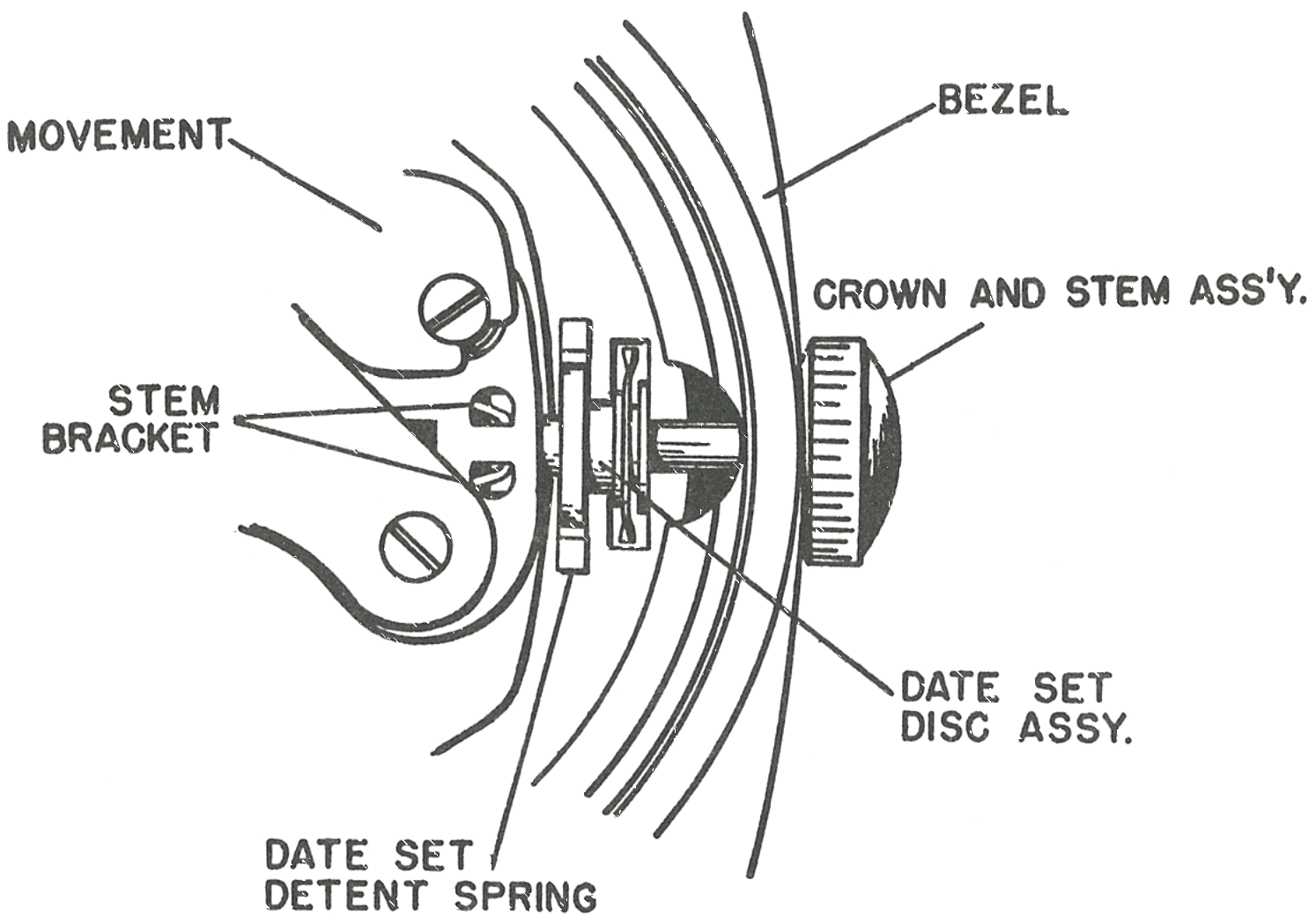
Be careful to pick out the date set disc assembly and the date set detent spring after the crown and stem assembly is removed.
Turn the watch over and with a crystal lift remove the crystal from the bezel, lift out the reflector ring and then remove the dial and movement assembly. Note the position of the movement locating tabs inside the bezel to make reassembly easier.
Fig. 52.3 · Figure 1
2 · Off the Dial
Remove all hands from the assembly. Turn the movement over and, while holding the dial in place, bend the four dial legs up just enough to permit removal of the dial.
Turn the movement over so the dial is up and carefully lift off the dial. Note the position of the loose parts under the dial.
Remove in order: hour wheel washer, day frame assembly, date ring, day detent spring, date wheel stud, date wheel, hour wheel, center wheel.
Note: It is not necessary to remove the date lever and the date detent spring. The movement assembly may then be serviced as for the Model 50.
Fig. 52.4 · Figure 2
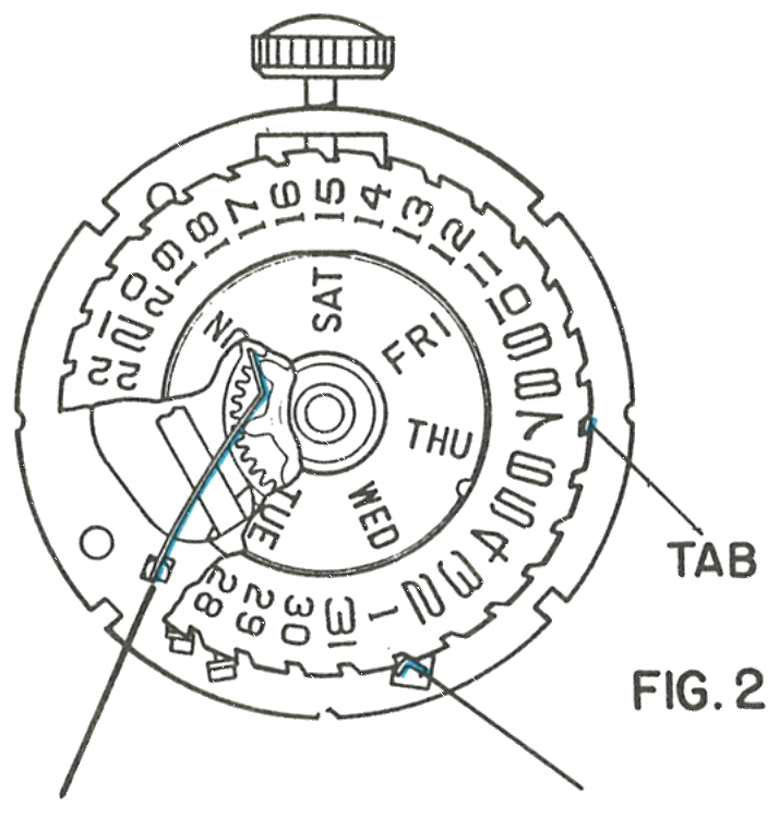
3 · Under the Day Frame
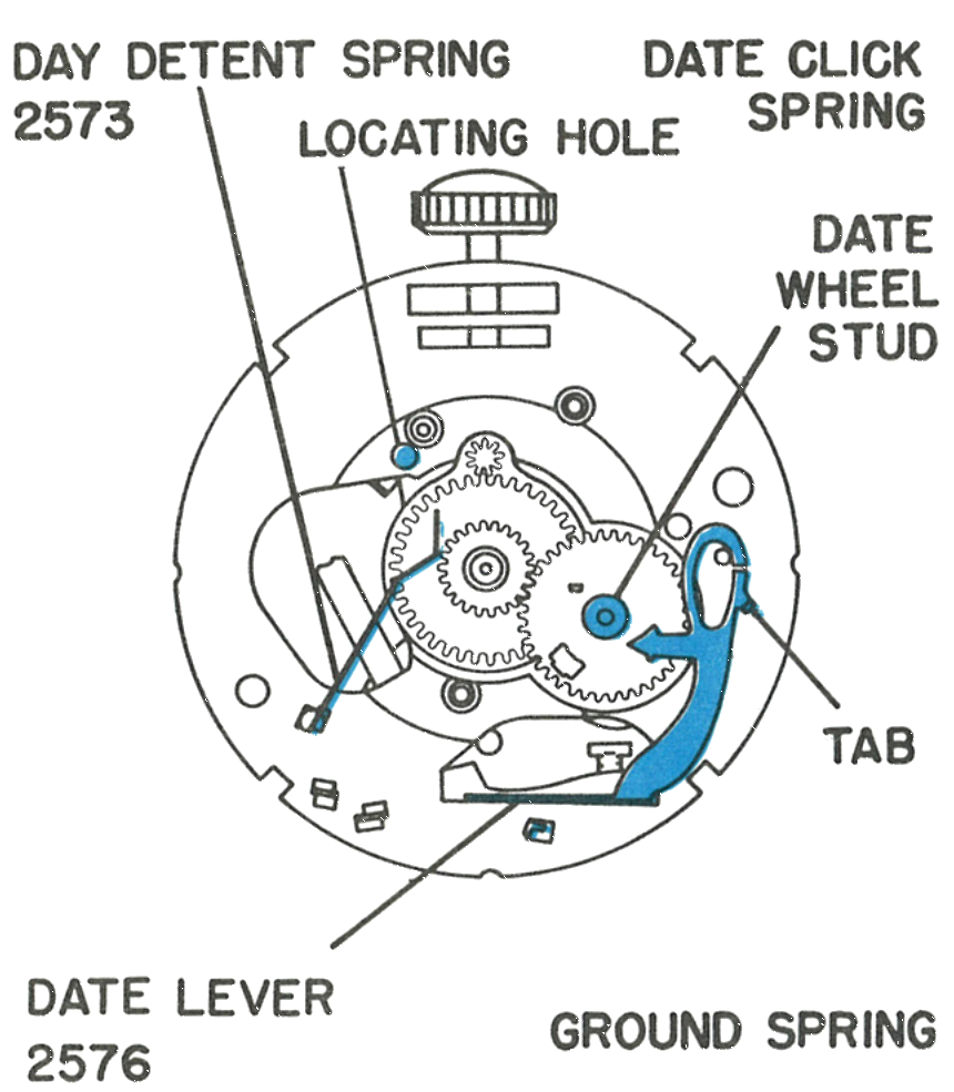
The day detent spring 2573, the date click spring, the locating hole, the date wheel stud, the tab and the date lever 2576.
Fig. 52.4 · Figure 3
4 · The Ground Spring
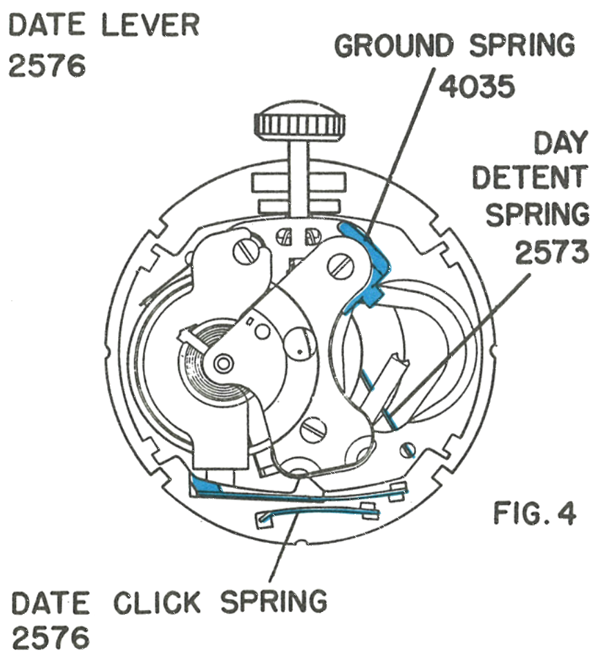
The energy cell ground spring 4035, the day detent spring 2573 and the date click spring 2576.
Fig. 52.4 · Figure 4
Reassembly
After the electronic movement has been serviced following the Model 50 procedures, care must be exercised in reassembling the dial and indexing parts.
First engage the setting stem and crown into the movement, but do not put in the date set disc assembly and date set detent spring at this time. Place the movement in the dial up position. Next, assemble in order: center wheel, hour wheel, date wheel, date wheel stud, hour wheel washer.
1 · The Day Detent Spring
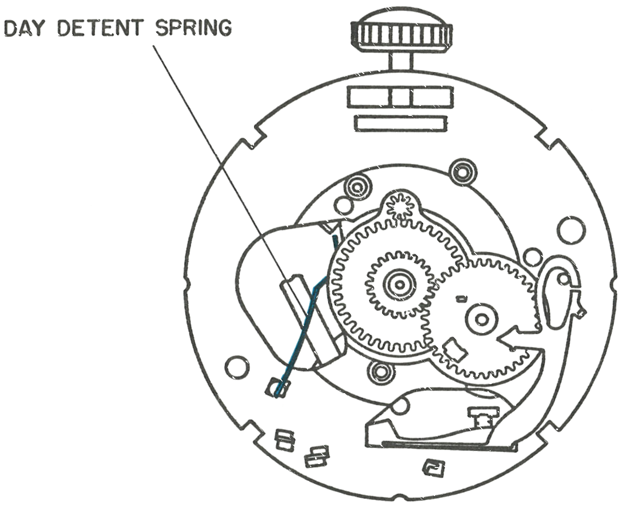
Insert the day detent spring into the proper slot in the dial rest and carefully deflect the end of the spring until it can be temporarily hooked under the edge of the dial rest.
Visually examine the date ring to be sure it is not bent or damaged. Place the date ring on the dial rest and position it against the end of the date click spring and the tab on the date lever, as near the centre as possible.
Examine the day frame assembly for damage and be sure the pinion is free to turn. Note the flat on the edge of the day frame assembly. Holding the assembly so the flat is toward the crown and parallel to the slot in the dial rest, place it on the movement. Apply light pressure on the day frame and move it slightly until it is centred and drops into place on the date wheel stud and into the hole in the dial rest.
Carefully place the dial on the movement so the dial legs are in the slots, then, holding the dial firmly in place, turn the movement over and bend the legs to secure the assembly. With a tweezer or small screwdriver, reach through the movement and release the hooked end of the day detent spring.
Fig. 52.5 · Figure 5
Examine the date ring for bends or damage. Place it on the dial rest against the end of the date click spring and the tab on the date lever, as near the centre as possible.
Examine the day frame assembly and be sure the pinion turns freely. Note the flat on its edge: hold it so the flat is toward the crown and parallel to the slot in the dial rest, place it on the movement, and apply light pressure while moving it until it centres and drops onto the date wheel stud and into the hole in the dial rest.
Place the dial so the legs are in the slots, hold it firmly, turn the movement over and bend the legs to secure it. With a tweezer or small screwdriver, reach through the movement and release the hooked end of the day detent spring.
Checking the date lever: Pull the setting stem into set, turn the movement dial down, turn the crown clockwise and watch the end of the date lever. It first deflects under the plate and then snaps out. When it snaps out, push in the crown, turn the movement over and assemble the hands to 12 o’clock.
Lubrication
Lubricant change, June 1974: Timex Service Bulletin No. 111 replaced the factory oil for this model. Moebius Synt-A-Lube oil is used instead of Elgin M56B oil. (It supersedes Bulletin No. 108.)
Junction of date lever and guide stud.
Both sides of the nose of the date lever.
Tab of the date lever, inside surface.
Date wheel at its bearing with the date wheel stud.
Date click spring where it contacts the date ring.
Contact surface of the day detent spring.
Elgin M56B is the watch lubricant used in the factory. Apply a small amount of watch oil at these points:
1 · A · Junction of date lever and guide stud2 · B · Both sides of the nose of the date lever3 · C · Tab of the date lever, inside surface4 · D · Date wheel at its bearing with the date wheel stud5 · E · Date click spring where it contacts the date ring6 · F · Contact surface of the day detent spring
Also: The bearing seat of the date wheel on the outer dimension of the day frame should be lubricated. On recasing, apply a small amount to one side of the cam lobe and to the bearing point of the cam on the stem.
Recasing & Checks
Remove the setting stem and crown assembly. Place the dial and movement into the bezel, being careful to position it so the movement locating tab is in the proper position. Position the reflector ring and replace the crystal.
Turn the watch over and place the date set detent spring in the slot in the dial rest. Position the date set disc assembly on the spring and insert the setting stem and crown through the bezel, through the date set disc and into the set position in the movement.
Examine the energy cell ground spring in the movement to be sure it is in the proper position to prevent a short circuit and to assure proper grounding.
Position the movement cover in the bezel, put in the Timex Energy Cell Type A and snap in the caseback. Push the crown into the run position and check that the watch runs, then test the function of the day change and the date change.
Cells: Use of an energy cell not meeting Timex specifications may cause a Timex watch to malfunction. Since the watch contains permanent magnets, no attempt should be made to demagnetize it.
This guide is based on the original Timex factory service manual for the Model 52 movement.