
Day and Date on the DYNABEAT
The Timex Model 255 is a 13½ ligne round high frequency electric day and date movement. The basic Model 255 movement is similar to the Model 253 movement, but differences exist in order to provide the day and date features.
For the high frequency electric movement itself, its contact system, its index train, cleaning and lubrication, see the Model 253 guide.
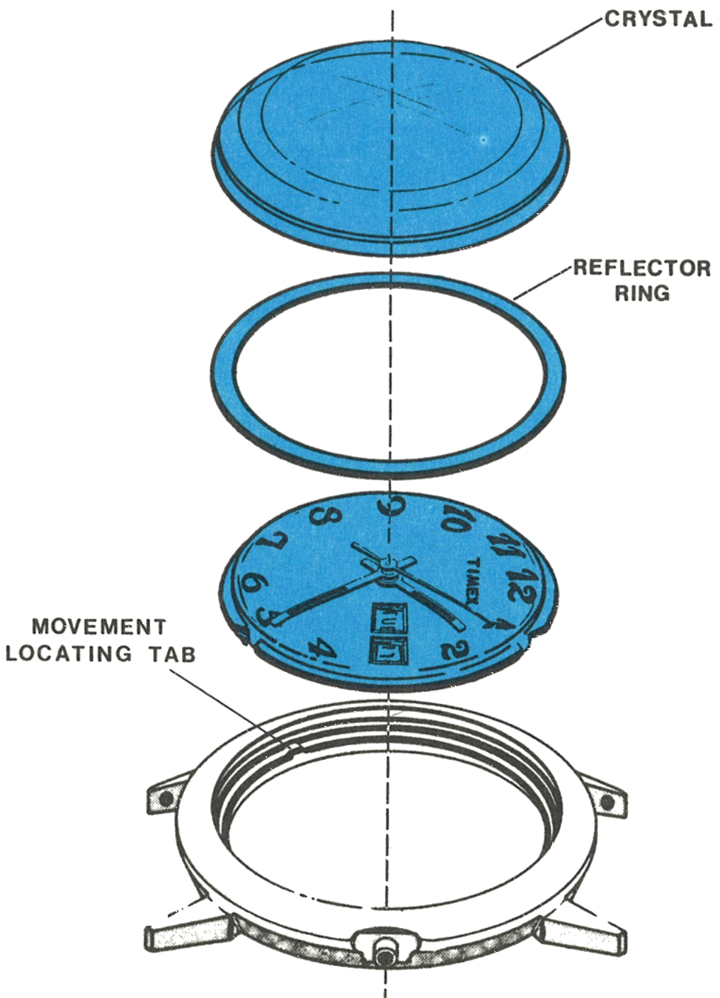
Exploded View
Everything below the numbered parts is the Model 253 movement.
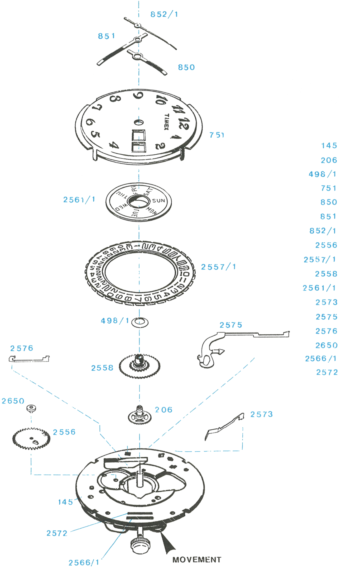
Disassembly
The Caseback and Cell
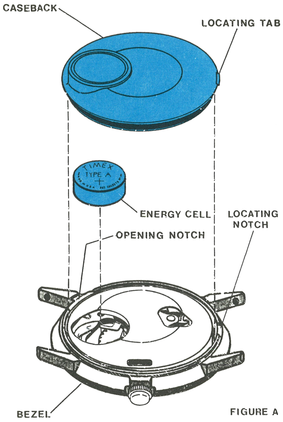
Insert a blade into the opening notch on the bezel and pry the caseback off. The locating tab on the caseback is used for orientation of the back during reassembly.
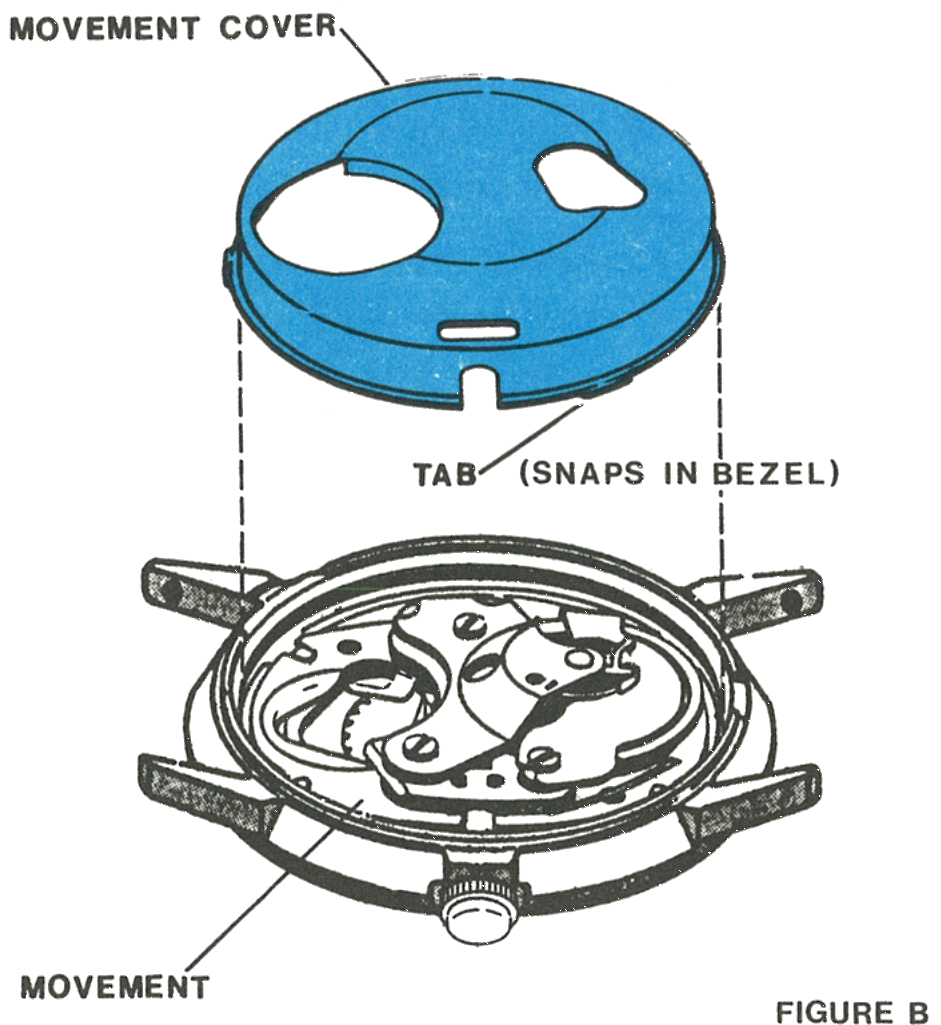
Remove the energy cell, then lift off the movement cover. The cover is held in place by two tabs which snap into recesses in the bezel.
The Movement Cover
The cover and the tab which snaps into the bezel, with the movement beneath.
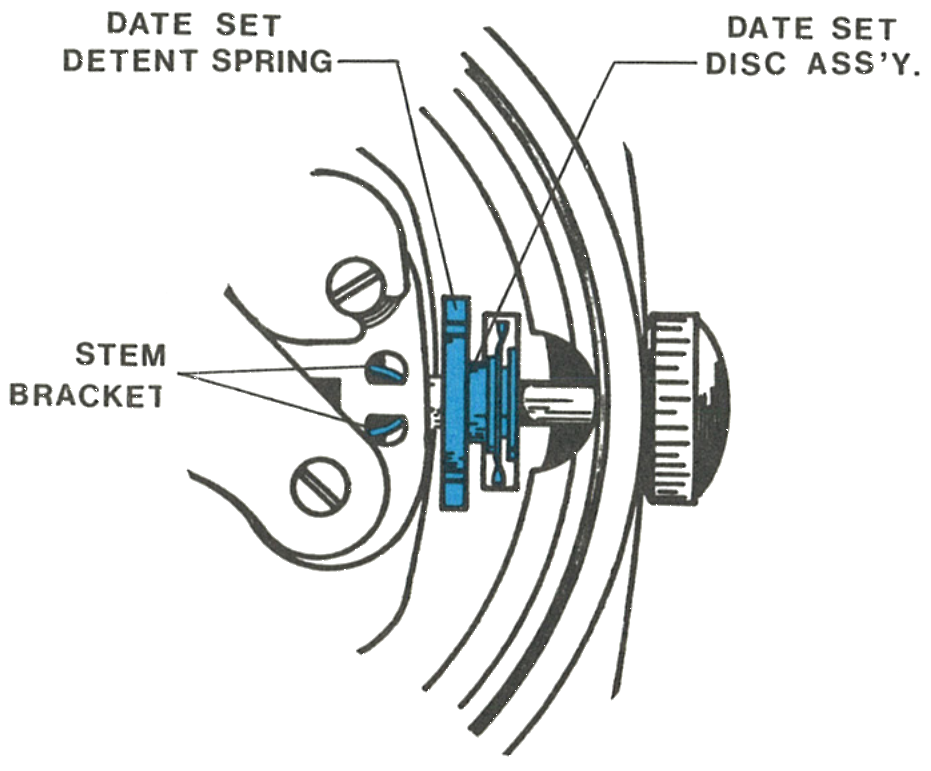
The Stem and Date Set Disc
Note the position of the date set disc assembly and the date set disc spring before touching anything.
The stem is held in position by the stem bracket. Release the stem from the stem bracket with a tweezer, as described for the Model 253.
Remove the date set disc assembly and the date set detent spring.
Out Through the Crystal
After these parts are removed, the movement can be removed through the crystal side of the case. Remove the crystal with a crystal seating tool and then lift the reflector ring and movement free of the case.
Off the Dial
Remove all hands. Bend the four dial tabs enough to free the dial from the movement.
Turn the assembly over and carefully lift the dial off the movement, noting the position of the parts underneath.
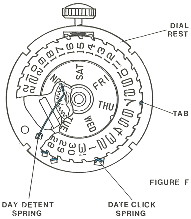
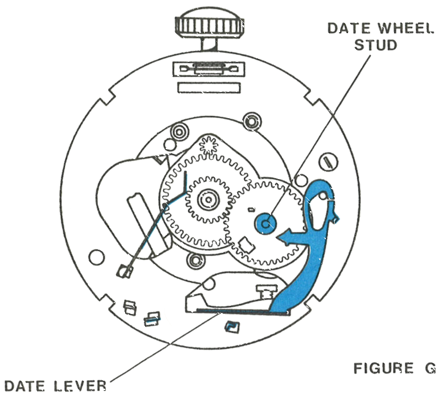
Remove in order: hour wheel washer, day frame assembly, date ring, day detent spring, date wheel stud, date wheel, hour wheel assembly, center wheel assembly.
The Date Lever
The date wheel stud, tab and date lever on the plate.
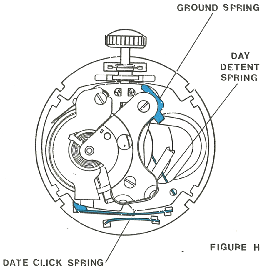
The Ground Spring
The energy cell ground spring, day detent spring and date click spring.
Reassembly
Assemble the crown and stem assembly to the movement, but do not put in the date set disc assembly or date set detent spring at this time. Assemble in order: center wheel assembly, hour wheel assembly, date wheel, date wheel stud, hour wheel washer.
The Day Detent Spring
Insert the day detent spring into the proper slot in the dial rest and carefully deflect the end of the spring until it can be temporarily hooked under the edge of the dial rest.
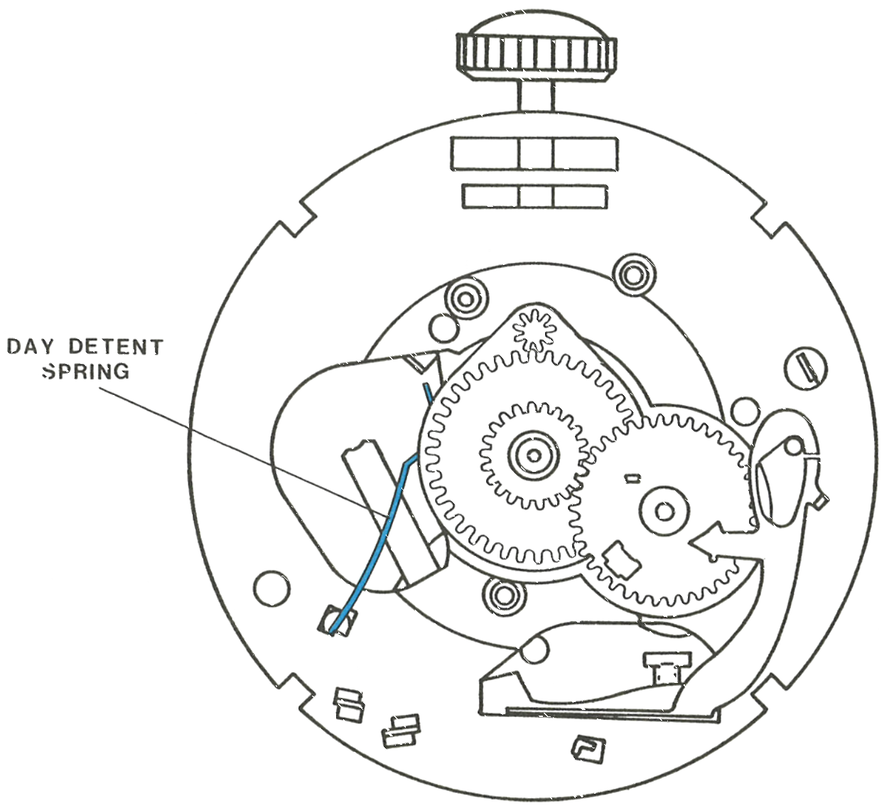
Visually examine the date ring to be sure it is not bent or damaged. Place the date ring on the dial rest and position it against the end of the date click spring and the tab on the date lever, as near the centre as possible.
Examine the day frame assembly for damage and be sure the pinion is free to turn. Note the flat on the edge of the day frame assembly. Holding it so the flat is toward the crown and parallel to the slot in the dial rest, place it on the movement. Apply slight pressure and move it slightly until it is centred and drops into place on the date wheel stud and into the hole in the dial rest.
Carefully place the dial on the movement so the dial legs are in the slots, then, holding the dial firmly in place, turn the movement over and bend the legs to secure the assembly. With a tweezer or small screwdriver, reach through the movement and release the hooked end of the day detent spring so it will engage the teeth of the day frame assembly.
Lubrication
Apply a small amount of non-spreading watch oil; Moebius Synt-a-lube is used in the factory.
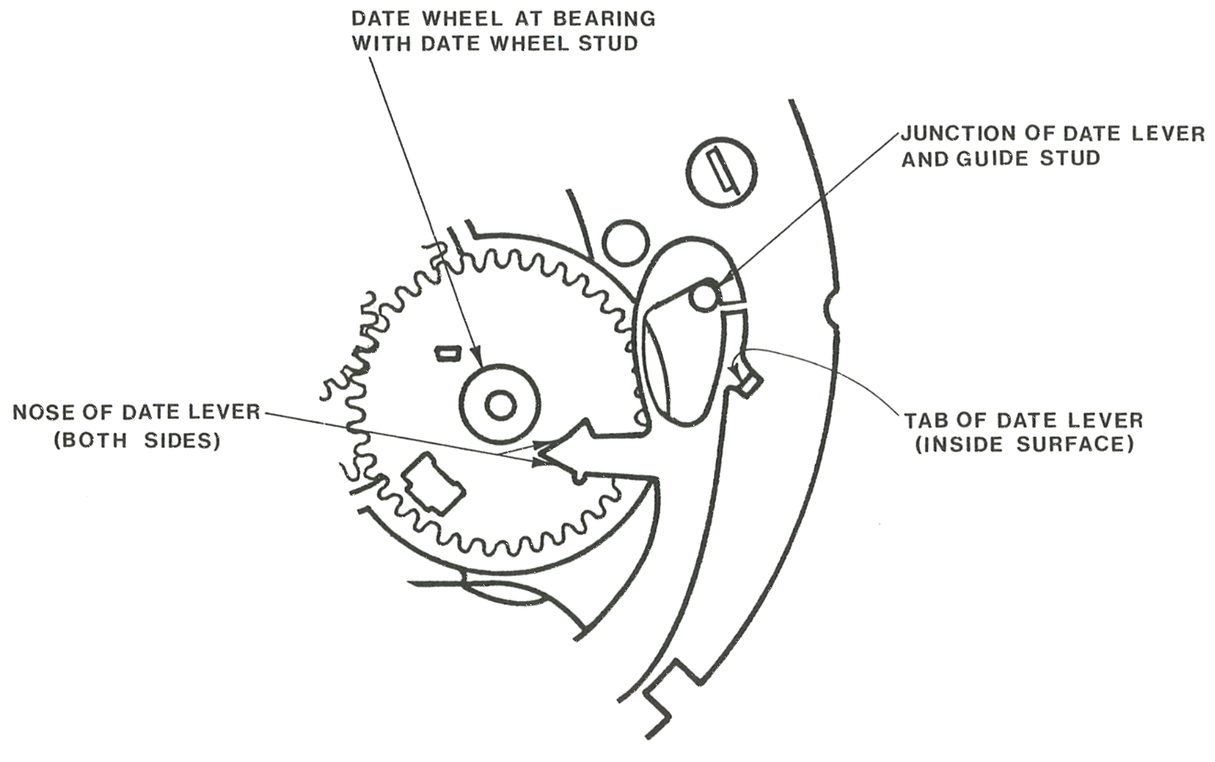
The Six Points
Junction of date lever and guide stud.
Both sides of the nose of the date lever.
Tab of the date lever, inside surface.
Date wheel at its bearing with the date wheel stud.
Date click spring where it contacts the date ring.
Contact surface of the day detent spring.
Recasing & Checks
Pull the setting stem with crown into the set position, then, with the movement in the dial down position, turn the crown clockwise and observe the movement of the end of the date lever. The end of the date lever first deflects under the plate and then snaps out. When it snaps out, push in the crown, turn the movement over and assemble the hands at the 12 o’clock position.
Remove the setting stem with crown assembly. Place the dial and movement assembly into the bezel, being careful to position it so the movement locating tab is in the proper position. Position the reflector ring and replace the crystal.
Turn the watch over and place the date set detent spring in the slot in the dial rest. Position the date set disc assembly on the spring and insert the setting stem and crown through the bezel, through the date set disc, through the date set detent spring, and into the set position in the movement.
Examine the energy cell ground spring in the movement to be sure it is in the proper position to prevent a short circuit and to assure proper grounding. Position the movement cover in the bezel, put in a Timex energy cell Type A and snap in the caseback. Push the crown into the run position and check that the watch runs, then check the function of the day change and the date change.