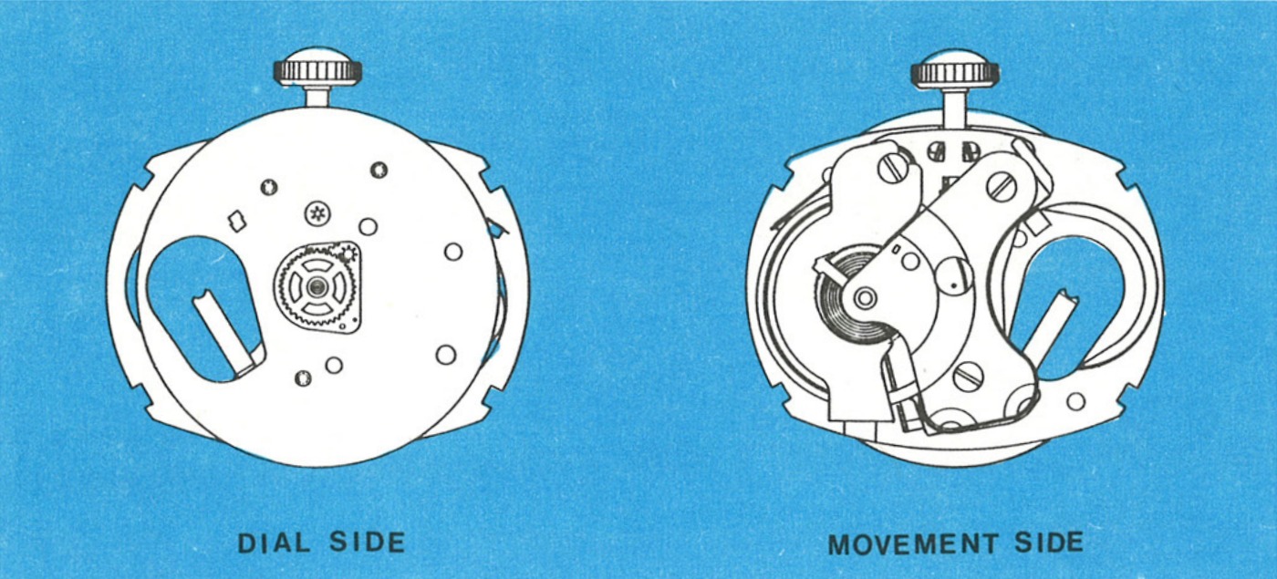
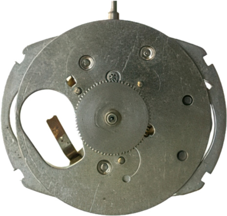
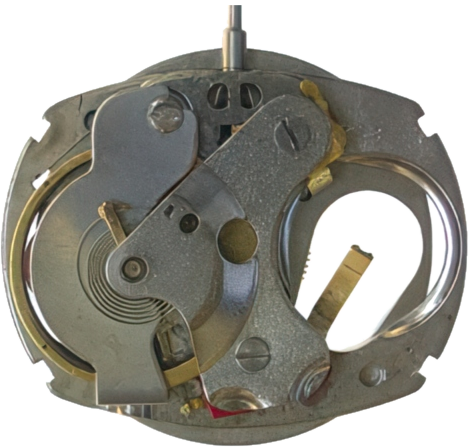
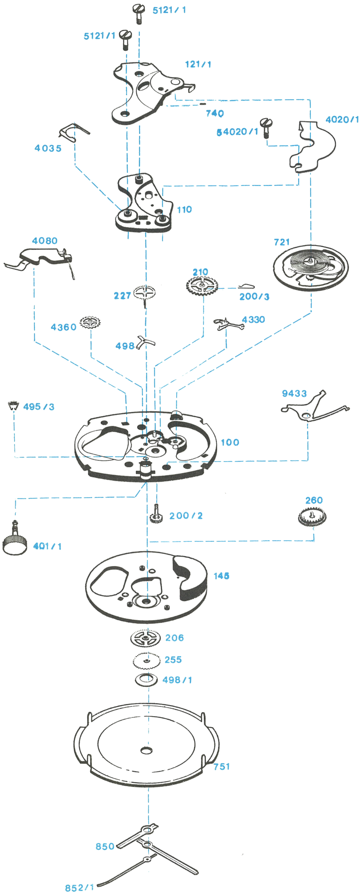
The Timex Model 253 is a 9¾ x 12¾ ligne electric watch movement featuring a high frequency balance system. It operates at a rate of 28,800 beats per hour. The rate can be checked on all conventional watch rate recorders having a setting for 28,800 beats per hour, and may also be checked on some recorders using a setting for 14,400 or 21,600 beats per hour.
What is different: In the Model 253 the contact spring, seconds wheel, index wheel and balance wheel assemblies differ from the similar Model 40 and Model 50 parts. The rest of the architecture is shared.
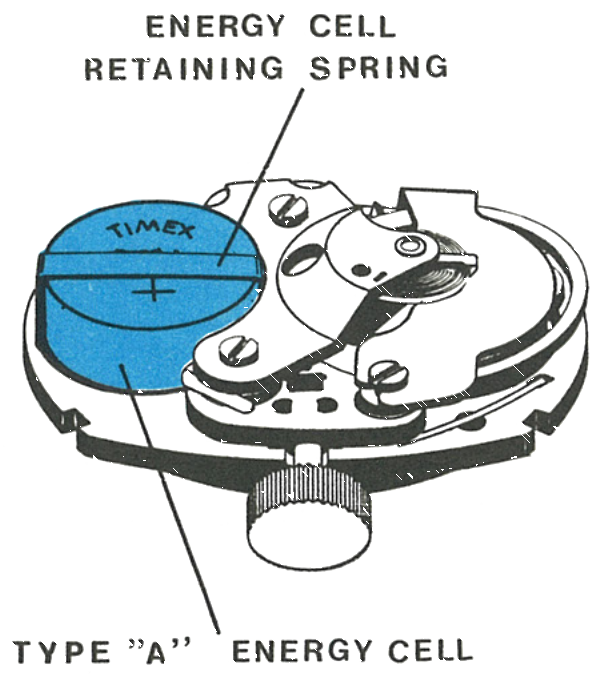
The Model 253 is powered by a Timex energy cell Type A. Timex recommends replacement only with the genuine Type A cell; use of a cell not meeting Timex specifications may cause the watch to malfunction. The Timex code number on the edge of the dial gives the catalog number, movement number and year of manufacture.
Caution: Since the watch contains permanent magnets, no attempt should be made to demagnetize it.
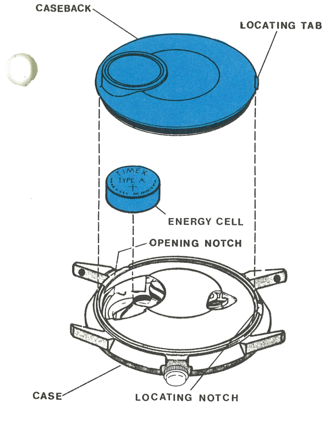
Insert a blade into the opening on the bezel and pry the caseback off. The locating tab on the caseback is used for orientation of the back during reassembly.
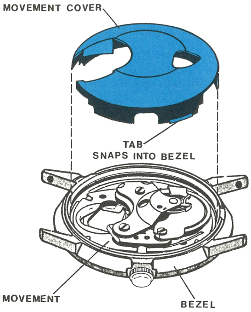
Remove the energy cell. Lift off the movement cover; it is held in place by two tabs which snap into recesses in the bezel.
Note: Any energy cell with a voltage of less than 1.5 volts, or one in service in excess of one year, should be replaced. Use of an energy cell not meeting Timex specifications may cause the watch to malfunction.
Fig. 253.3 · Figure A
2 · The Movement Cover
The cover and the tab which snaps into the bezel, with the movement beneath.
Fig. 253.3 · Figure B
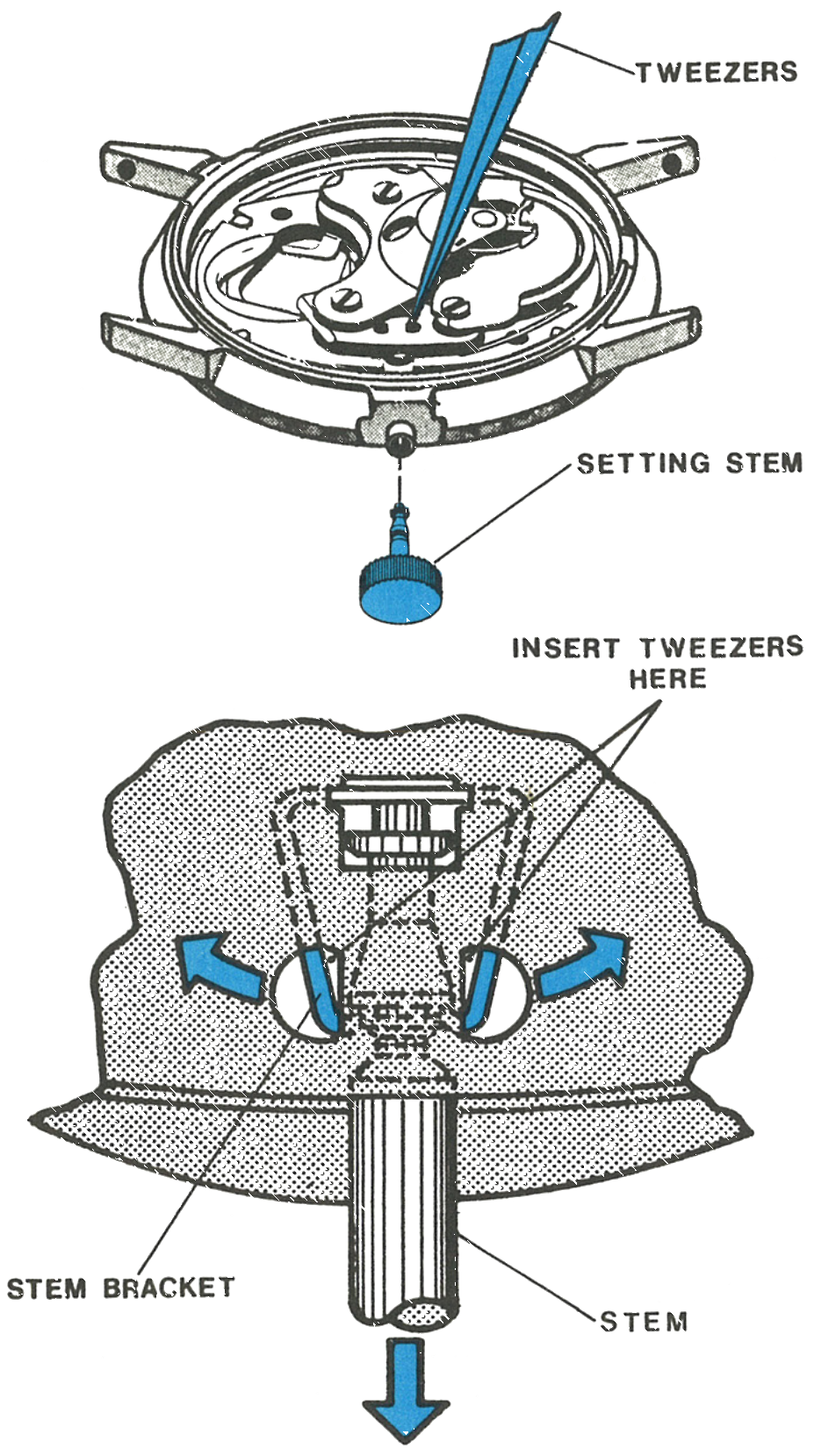
3 · Releasing the Stem
The stem is held in position by the stem bracket. Pull the stem out into the set position and continue to maintain a slight outward pull.
Place the points of a heavy tweezer into one side of the stem bracket and push the bracket aside to release one side of the stem. Continue to pull the stem outward and use the tweezer points to release the other side. The stem will now pull free of the movement and bezel.
Fig. 253.4 · Figures C and D
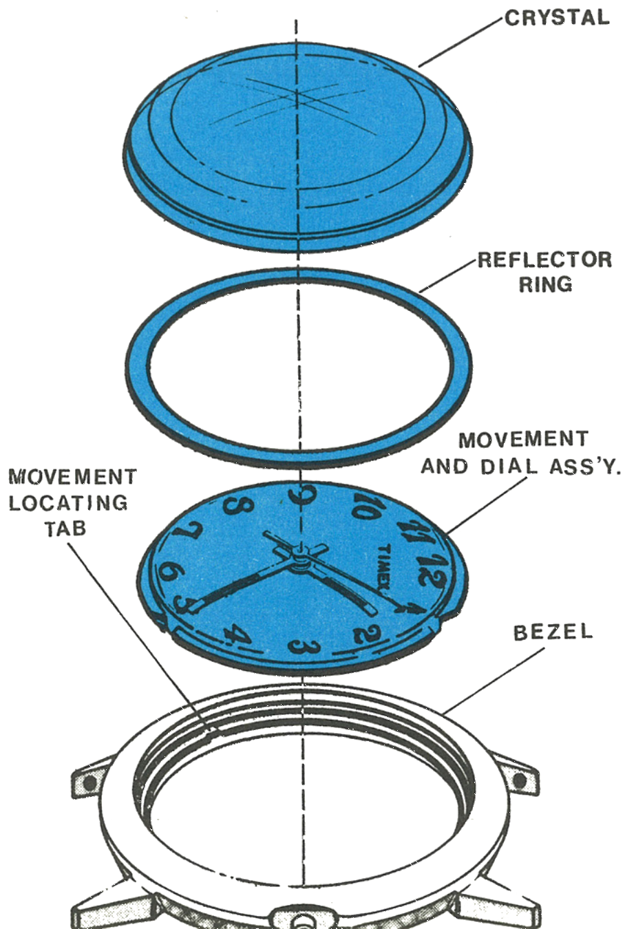
4 · Out Through the Crystal
After the stem is removed, the movement can be removed through the crystal side of the bezel. Remove the crystal with a crystal seating tool and then lift the reflector ring and movement free of the bezel.
Note: Note the position of the movement locating tabs inside the bezel. Tabs should align in the notches of the plate when reassembling.
Fig. 253.4 · Figure E
5 · The Dial
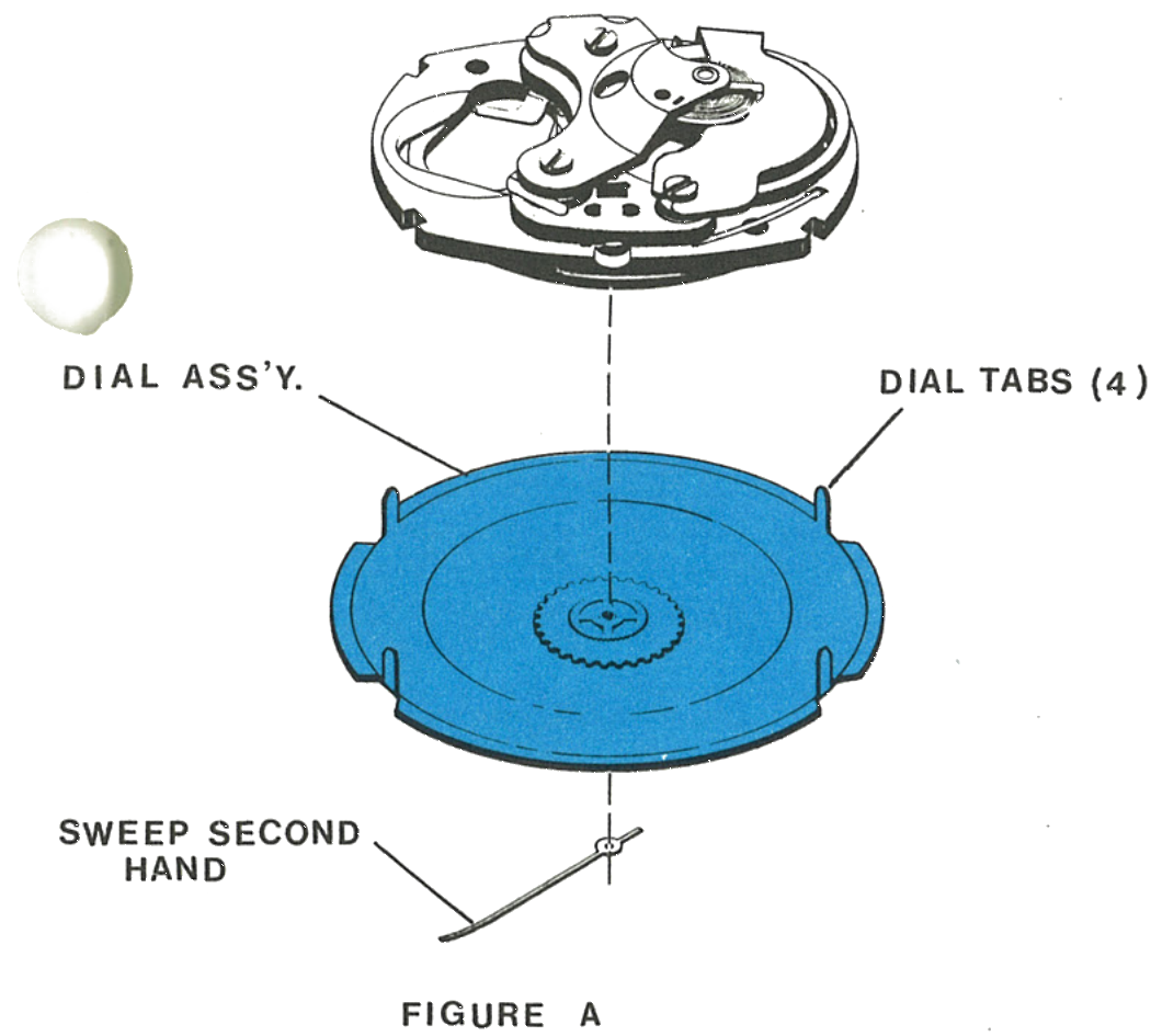
Remove the sweep second hand; the minute and hour hands need not be removed.
Straighten the four dial tabs enough to remove the dial from the movement.
Fig. 253.5 · Figure A
6 · The Shunt Bridge
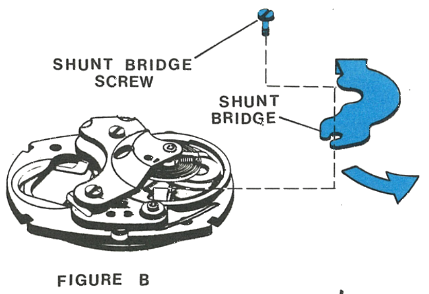
Remove the shunt bridge screw. Lift the screw end of the shunt bridge off its post and carefully slide the shunt bridge from the movement, noting the tab on its end which engages the plate.
Fig. 253.5 · Figure B
7 · The Balance
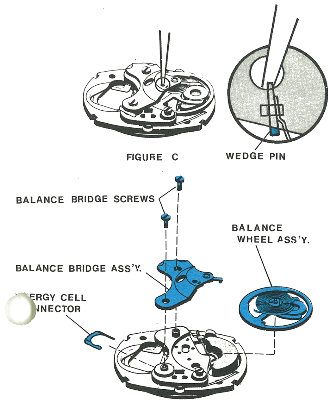
Remove the hairspring wedge pin; do not distort either the pin or the hairspring. Note the hole in the balance bridge which permits access to the wedge pin.
Rotate the balance wheel carefully until the hairspring tail is free of the hairspring bracket and the regulator.
Note the position of the energy cell connector, then remove the two balance bridge screws, remove the connector, lift off the balance bridge assembly and carefully remove the balance wheel assembly.
Note: If the wedge pin cannot be loosened through the hole, remove the two balance bridge screws and take the balance bridge and wheel assembly off the movement to reach it.
Fig. 253.5 · Figures C and D
Cleaning
The best way to clean the Model 253 movement is to disassemble it only to the point of removing the balance bridge and the balance wheel assembly. The movement should be placed in the watch cleaning machine, including ultrasonic baths, preferably on edge to insure proper drainage of the fluids. The movement must be immersed in two sets of rinsing fluid, and the final rinsing solution must be absolutely clean. After cleaning is completed, the movement must be thoroughly dried.
The balance wheel assembly must be cleaned separately in order to prevent damage to the balance staff points and the hairspring. Other metal parts may be cleaned in the same manner as the movement. Only standard watch cleaning solutions should be used.
Caution: Care must be exercised when cleaning cases, dials, hands and special rings which may contain materials other than metal, because paint, lacquer and plastic finishes can be damaged by some standard cleaning solutions.
Lubrication
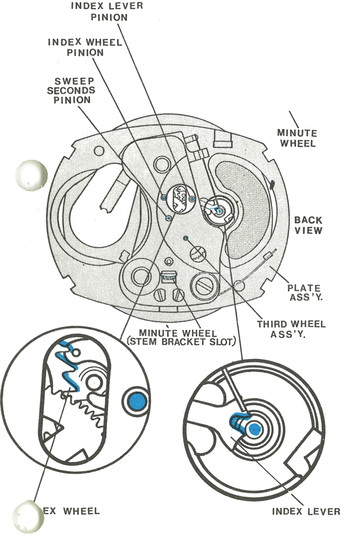
Apply non-spreading type oil, Moebius Synt-a-lube in the factory, to the minute pinion stud at the top of the minute pinion; both pivots of the index lever; both pivots of the index wheel pinion; both pivots of the sweep seconds pinion; the back pivot of the third wheel assembly; the junction of the minute wheel with the dial ring; the junction of the minute wheel with the plate assembly, through the stem bracket slot in the train bridge; the index wheel on the driving face of three teeth; the index lever fork where it contacts the impulse pin; and the friction washer and sweep second pinion bearing surface at their junction.
1 · Front View
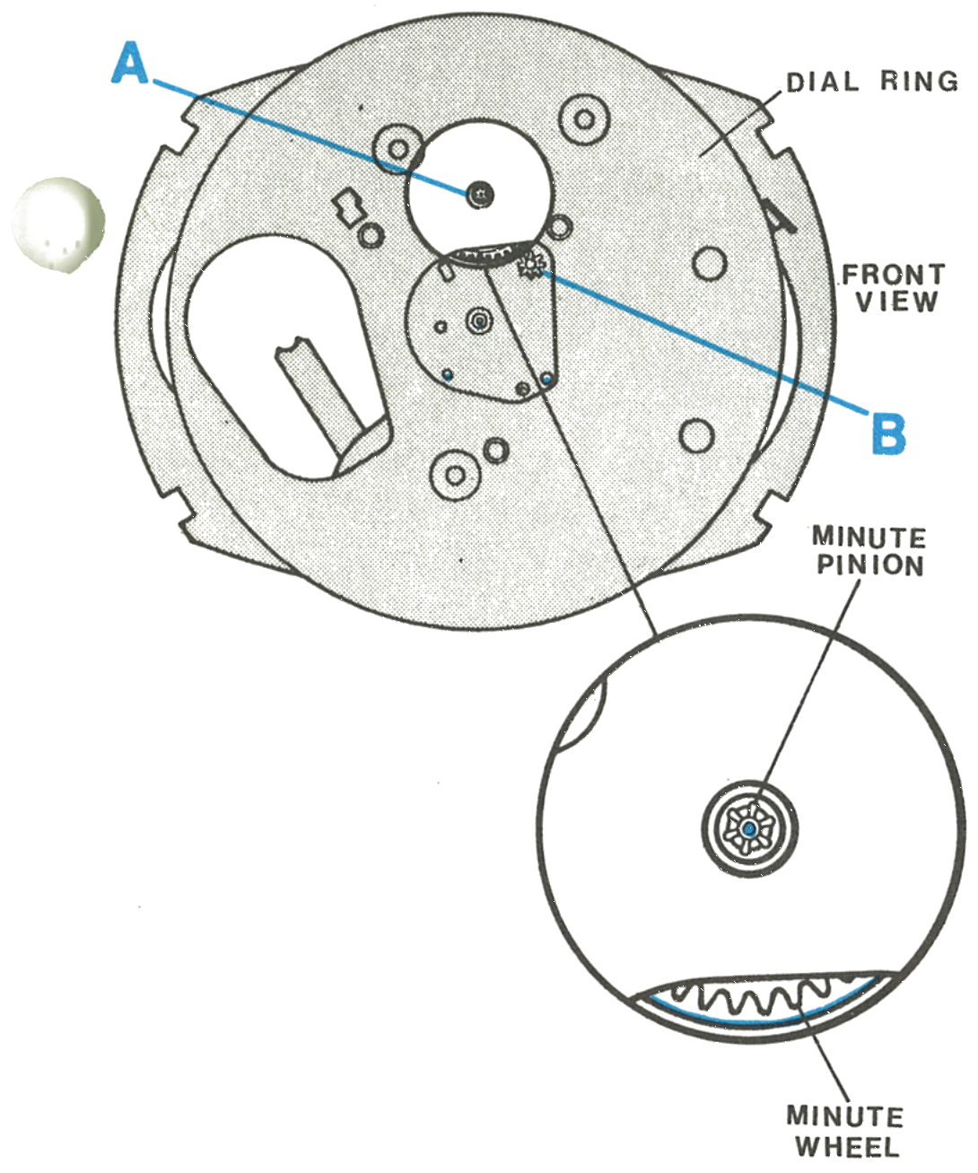
The dial ring, minute pinion, index lever pinion, index wheel pinion, sweep seconds pinion and minute wheel.
Fig. 253.7 · Front View
2 · Back View
The plate assembly, minute wheel through the stem bracket slot, third wheel assembly, index wheel and index lever. Point A is the root of the minute pinion teeth and point B the friction pinion at its junction with the plate assembly.
Fig. 253.7 · Back View
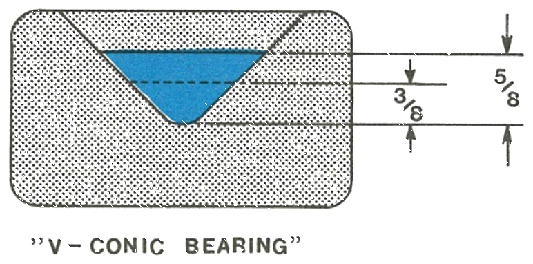
3 · Filling the V-Conic Bearings
Fill the V-conic bearings three eighths to five eighths full, by depth.
Apply spreading type oil, Woods AAAA in the factory, to the root of the minute pinion teeth, point A in the front view, to lubricate the minute wheel pinion pivot; and to the friction pinion at its junction with the plate assembly, point B.
Apply watch grease, Hamilton PML in the factory, to the set stem bracket, set stem teeth and bearing surface below the teeth, prior to assembly of the stem to the watch head.
Fig. 253.7 · V-Conic
Apply spreading oil, Woods AAAA, to the root of the minute pinion teeth (point A) and the friction pinion at its junction with the plate (point B). Apply watch grease, Hamilton PML, to the set stem bracket, set stem teeth and bearing surface before assembling the stem.
Water resistant models: Apply grease, Moebius special lubricant, to half of the exposed circumference of the crown gasket before assembly of the stem to the watch head.
Operation & Contact
The manual gives a bench test with a stated pass mark.
1 · Running on the Bench
Disassemble as far as removal of the dial. Replace the stem, push into the run position and place the movement on a suitable movement ring. Place the energy cell in position and secure with an energy cell retaining spring, available on request from the Timex material sales division.
With the energy cell in place the movement should start to run and the balance wheel assembly will oscillate. If it fails to start immediately, slight rotation of the watch may be necessary. Check that the sweep second staff is moving.
Note: A minimum balance amplitude of 480° indicates the watch is in satisfactory condition.
Fig. 253.8 · Figure A
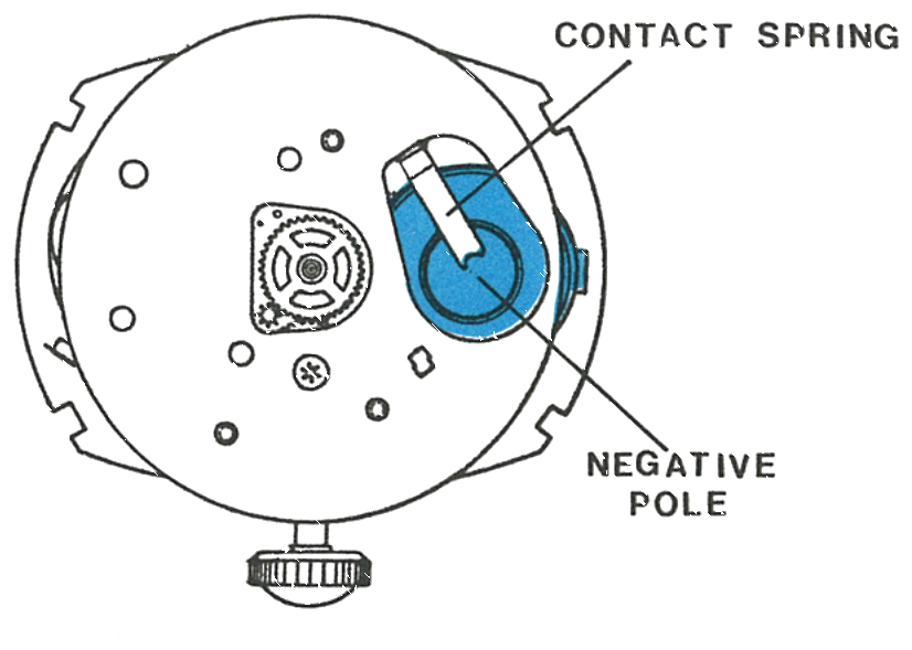
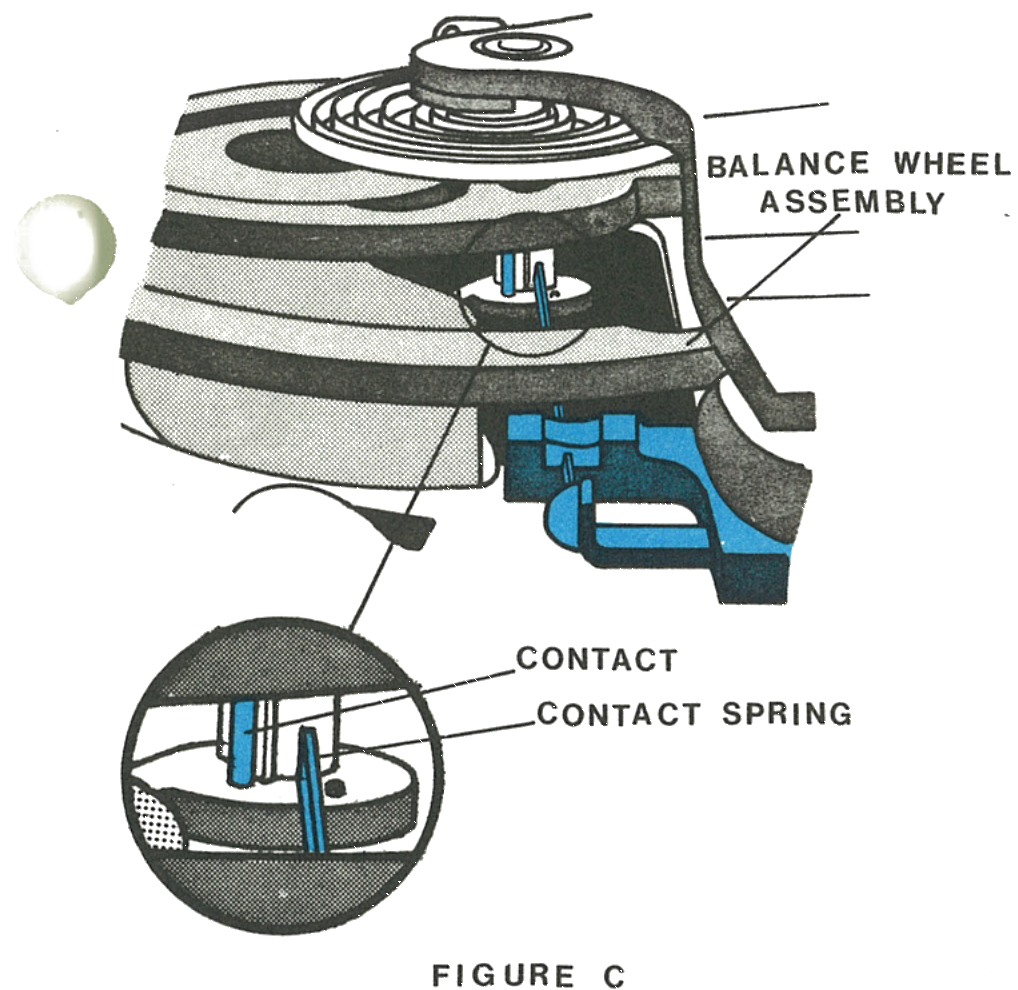
2 · Where the Cell Touches
The negative pole of the energy cell must touch the contact spring assembly. Never permit metallic contact between insulated and uninsulated parts of the movement, as the short circuit will reduce the life of the cell.
Fig. 253.8 · Figure B
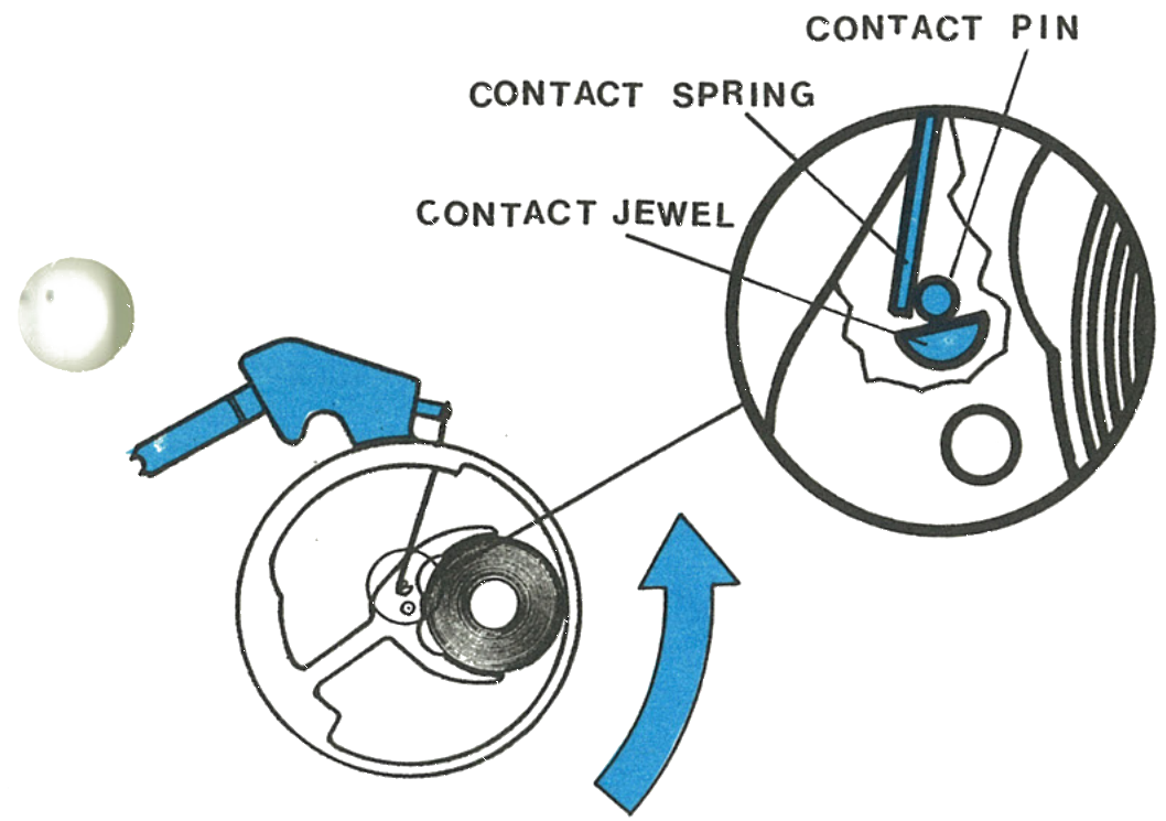
3 · The Contact Closing
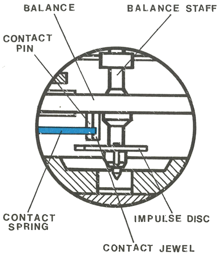
Rotate the balance assembly slowly from the rest position using very light pressure, a clean brush. The instant the contact spring touches the contact pin on the balance, current flows through the balance coil. The current induces a magnetic field which opposes the field of the permanent magnet and imparts an impulse to the balance assembly.
Fig. 253.9 · Figure C
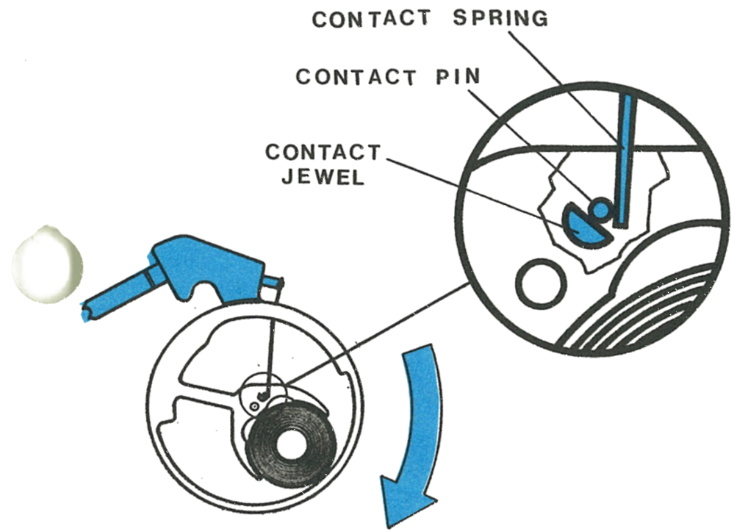
4 · The Contact Jewel
The purpose of the contact jewel is to limit the contact between the contact spring and the contact pin, so that the flow of current occurs at the proper position during the rotation of the balance assembly.
Fig. 253.9 · Figure D
5 · The Return Stroke
After the balance returns to its neutral position the same contact process is repeated in the opposite direction. This action is the source of mechanical power to drive the movement.
Fig. 253.9 · Figure E
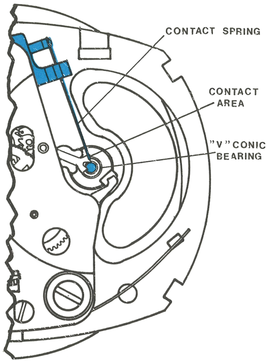
6 · Where the Contact Spring Points
The position of the contact spring is critical. The spring must be pointing exactly at the centre of the balance staff, or V-conic bearing.
7 · Centred Between Disc and Balance
Caution: Protect it from scratches and deforming, avoid excessive bending, and do not touch the contact area. Do not attempt to adjust its length, and permit no watch lubricant near the contact pin, jewel or spring.
Fig. 253.10 · Figure F
8 · G · Centred Horizontally
Fig. 253.10 · Figure G
The Index Train
1 · Taking the Train Bridge Off
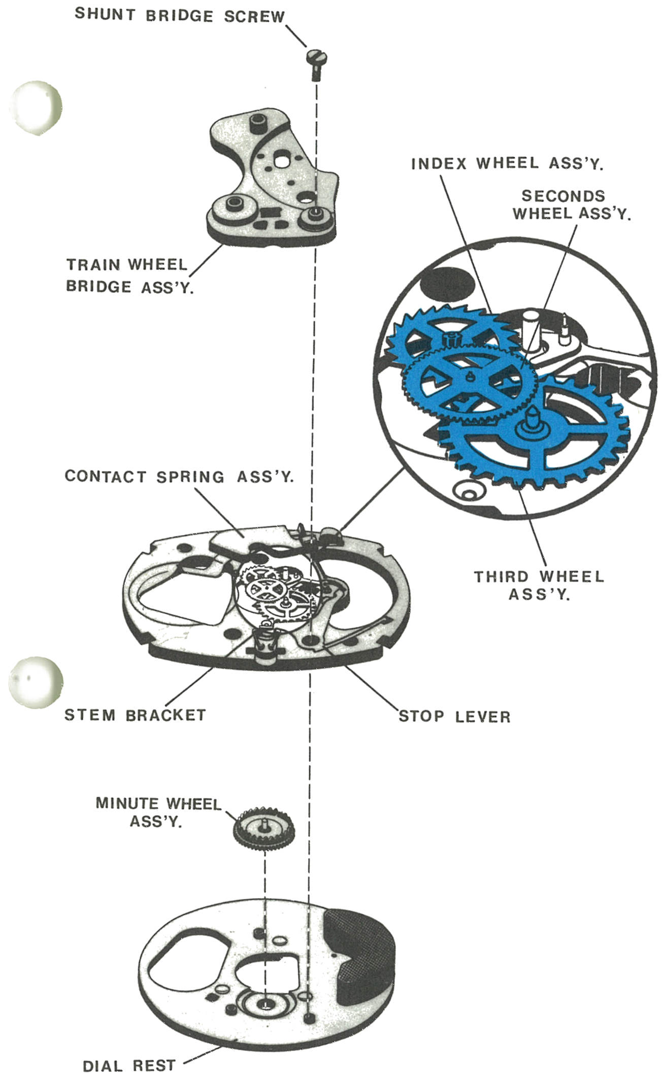
Remove the balance bridge and balance wheel assembly, then the shunt bridge screw. Lift off the train wheel bridge being careful not to disturb the loose parts, and note the position of the various parts on the plate assembly.
The dial rest and minute wheel assembly may be removed from the bottom of the plate assembly without disturbing the gear train. Lift the stem bracket, stop lever and contact spring assembly off the plate assembly without disturbing the gear train.
The third wheel assembly is driven by the pinion on the seconds wheel assembly. The seconds wheel assembly is driven by the pinion on the index wheel assembly.
Fig. 253.11 · Figure H
2 · Clockwise: the Advance
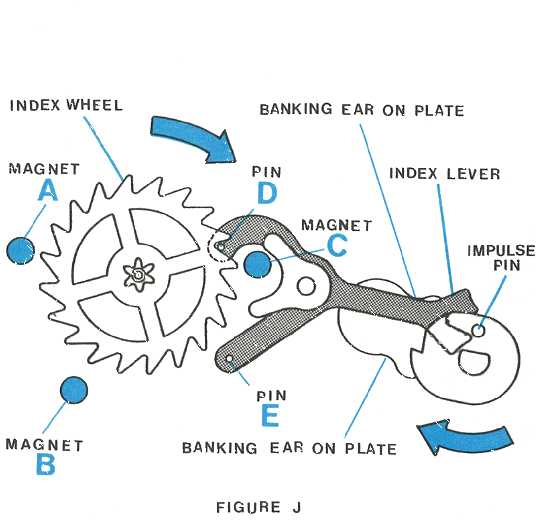
The impulse pin on the balance assembly, when moving clockwise, engages with the fork on the index lever and moves the lever counterclockwise. Pin D on the index lever engages with the index wheel.
The three magnets, round pins mounted in the plate assembly and labelled A, B and C, attract the tips of the index wheel teeth and move the wheel clockwise the remaining part of a tooth. Magnet C also attracts the draw lever on the index lever and holds it in position until moved by the impulse pin.
Fig. 253.12 · Figure J
3 · Counterclockwise: the Correction
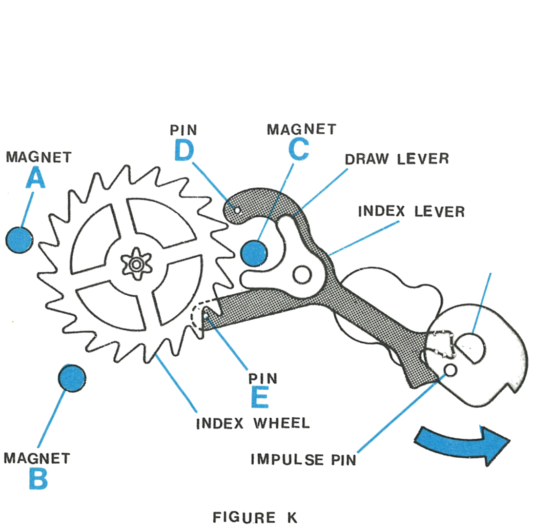
When the impulse pin moves counterclockwise it engages the fork and moves the index lever clockwise. Pin D moves out of engagement with the index wheel and pin E moves into engagement.
If the index wheel is not positioned correctly by the magnets, pin E turns the index wheel to the correct position so that the next engagement of pin D will advance the index wheel clockwise. Clockwise rotation of the index wheel drives the movement gear train.
Fig. 253.12 · Figure K
4 · The Friction Pinion
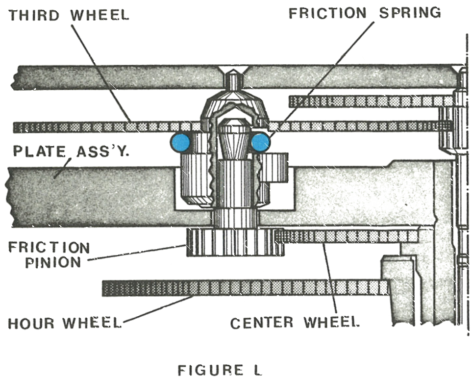
Setting friction for the dial train is provided by a spring connecting the friction pinion and the third wheel. The friction pinion and third wheel may be separated by lifting the friction pinion with tweezers; it is not necessary to remove the friction spring from the third wheel. To reassemble, press the friction pinion firmly back into place in the third wheel.
Fig. 253.13 · Figure L
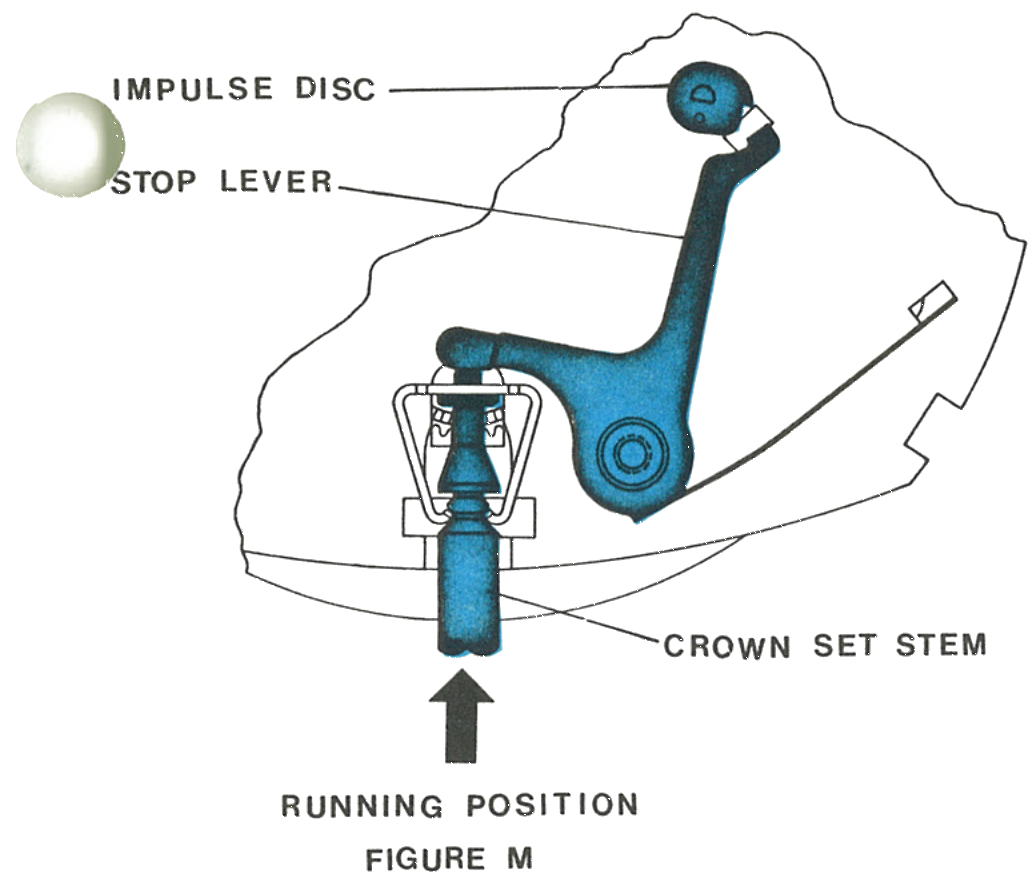
5 · Running Position
The balance stop mechanism is purely mechanical. In the running position the tip of the stem butts against the stop lever and keeps the tip of the stop lever away from the impulse disc.
Fig. 253.13 · Figure M
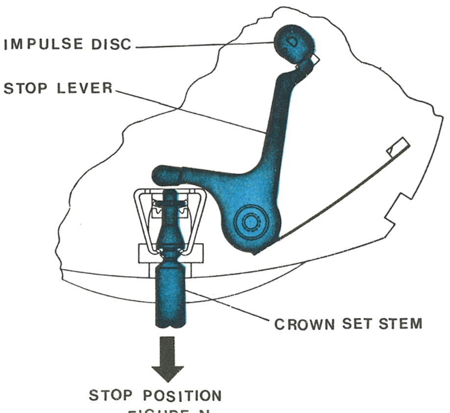
6 · Stop Position
With the stem pulled out into the set position, the tip of the stop lever butts against the impulse disc on the balance wheel assembly and stops it. In the stopped position there is no current drain to shorten the life of the energy cell.
Fig. 253.13 · Figure N
7 · The Seconds Wheel Friction Washer
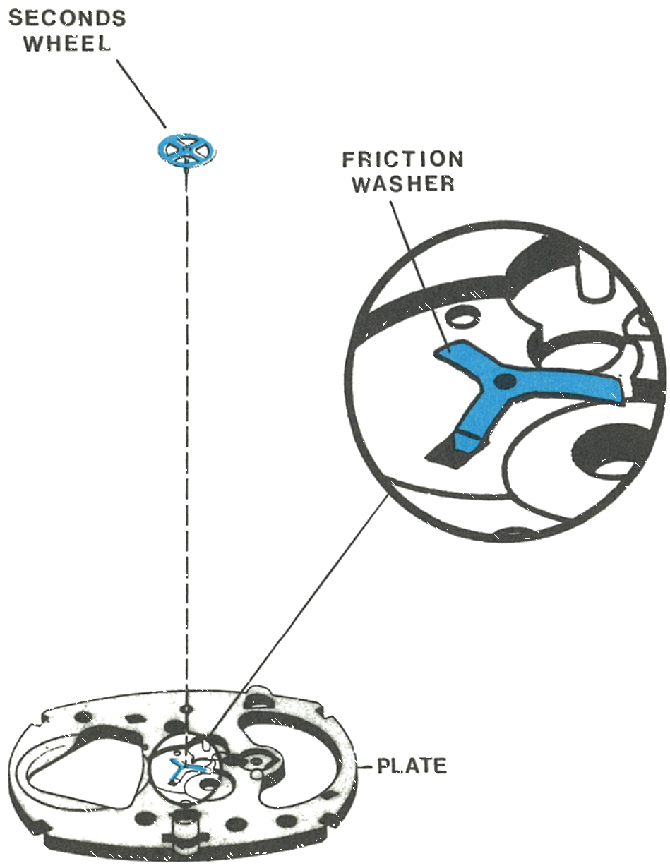
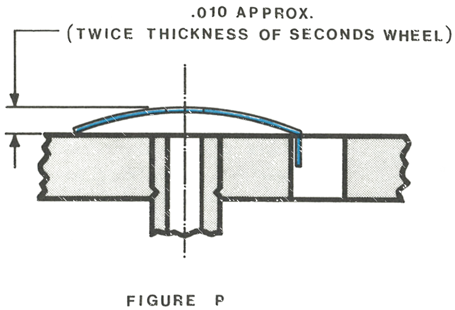
A friction washer is located between the plate and the seconds wheel, domed slightly. Check that it has not become damaged during disassembly. Too much friction will cause too great a drag on the movement; too little will cause an erratic sweep second hand action.
A tab on one leg of the friction washer fits into a slot in the plate to prevent it from turning.
Fig. 253.14 · Figure Q
8 · The Dome
The dome is .010 approximately, twice the thickness of the seconds wheel.
Fig. 253.14 · Figure P
Reassembly
Place the minute wheel assembly in the dial rest, then carefully position the plate assembly on top of the dial rest.
Train wheel bridge assembly, secured with the shunt bridge screw
1 · Minute wheel assembly in the dial rest, then the plate assembly on top2 · Third wheel assembly3 · Friction washer4 · Index lever assembly5 · Index wheel assembly6 · Seconds wheel7 · Stem bracket8 · Stop lever9 · Contact spring assembly10 · Train wheel bridge, secured with the shunt bridge screw
The third wheel: Place the friction pinion, pinion side down, on a flat anvil, place the plate assembly over it, then snap the third wheel with its friction spring onto the end of the pinion.
11 · Refitting the Balance
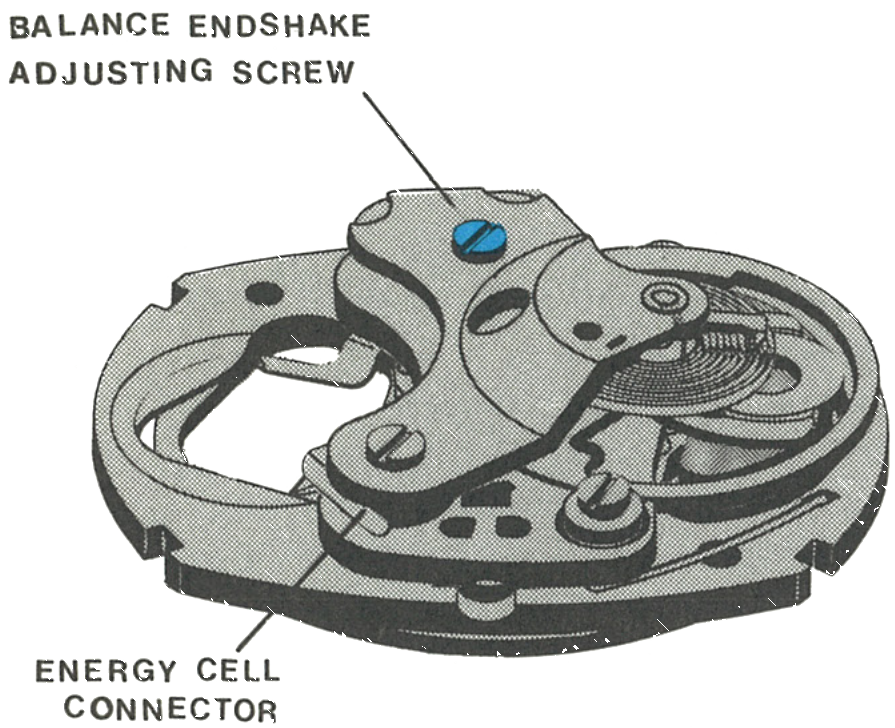
Assemble the balance bridge assembly to the movement with the two balance bridge screws, leaving the screws loose. Tilt the balance wheel assembly and carefully insert the pivot on the hairspring side into the V-conic bearing, then the other pivot into the other V-conic bearing.
Tighten the balance endshake adjusting screw enough to hold the balance wheel assembly in place, then place the energy cell connector in position.
Fig. 253.15 · Figure R
12 · The Hairspring and Regulator
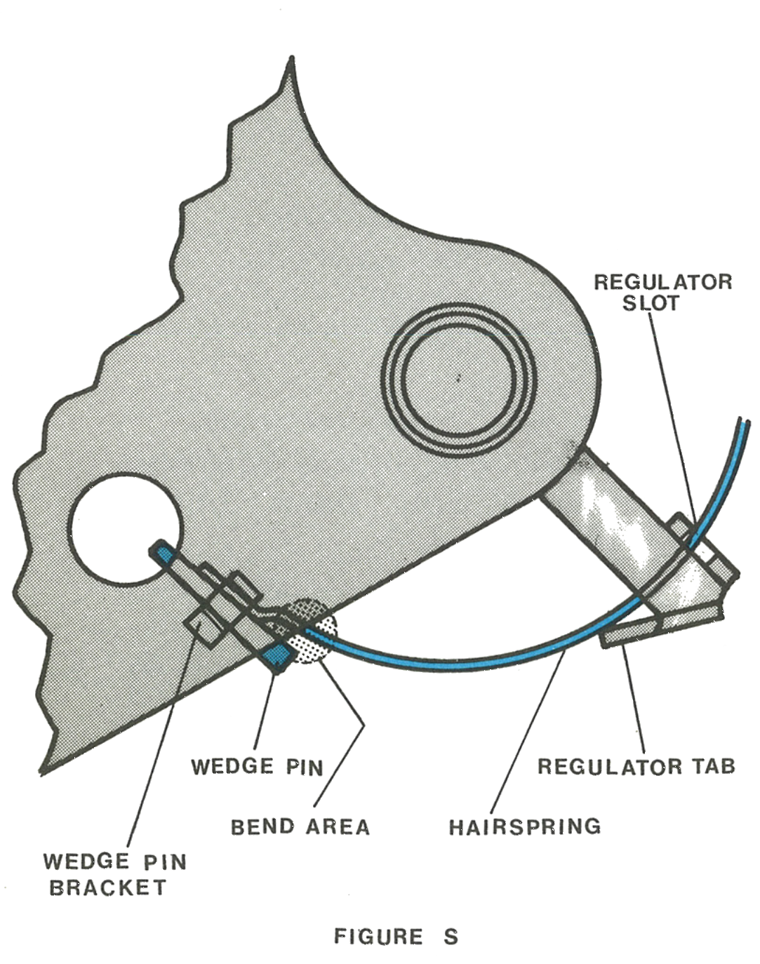
Insert the end of the hairspring into the slot in the regulator and then into the hole in the hairspring bracket by rotating the balance wheel and guiding the end of the spring. Check that the impulse pin is in the slot of the index lever, then secure the hairspring in the bracket with the wedge pin.
The hairspring should be levelled, centred and in light permanent contact with the inside edge of the regulator slot and the regulator tab. It must not leave those contact points at any time with the regulator within normal regulating range.
Adjust the level by grasping the spring as close as possible to the pinning point. To adjust centring, grasp 160° to 180° from the pinning point. To keep the spring in permanent contact with slot and tab, carefully bend the tab towards the centre of the spring.
Preposition the hands at 12 o’clock on the dial, then position the dial assembly on the movement so the dial tabs pass through the plate assembly. Hold the dial in place and bend the tabs to secure it on the plate. Drive the sweep second hand onto the end of the sweep second staff, being sure the hand is below the chamfer on the staff.
Place the movement and dial assembly in the case, being careful to position it on the locating tabs, and replace the crystal to secure the movement. Insert the crown and stem assembly with a turning motion to assure engagement in the stem bracket. Put a fresh Timex energy cell Type A in place, positive side up, position the caseback and snap it closed. Push the crown in and the watch will start; if it does not, slight rotation may be necessary to restart the mechanism.
Caution: Adjust the endshake with minimum downward pressure, which could damage the points of the balance staff. Loosen the shunt bridge screw, slide the shunt bridge under the hairspring and secure it.
Fig. 253.16 · Figure S
Preposition the hands at 12 o’clock, position the dial so the tabs pass through the plate, hold it and bend the tabs. Drive the sweep second hand onto the staff below the chamfer.
Place the movement in the case on the locating tabs and replace the crystal. Insert the crown and stem with a turning motion. Put a fresh Type A cell in place, positive side up, and snap the caseback closed. Push the crown in and the watch will start.
This guide is based on the original Timex factory service manual for the Model 253 movement.