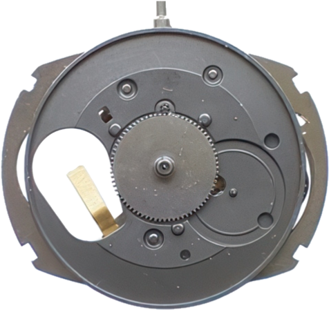
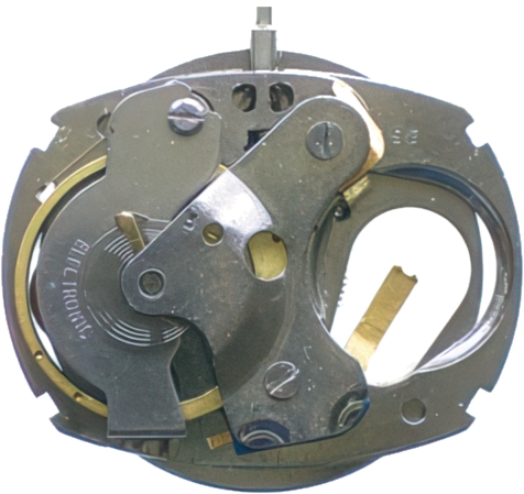
The Model 40 with a diode. Mechanically the same electric movement, magnet-assisted index wheel and all, but a semiconductor has been introduced into the balance wheel circuit to stabilise amplitude.
The Timex electronic has an hourly beat of 21,600. The large balance has a temperature compensated hairspring and the rate can be adjusted in the usual way by moving the regulator. It can be checked in all positions on a normal watch rate recorder, and dismantled and repaired with conventional tools. For checking the battery voltage, a high ohm volt meter of about 20,000 ohms per volt is sufficient.
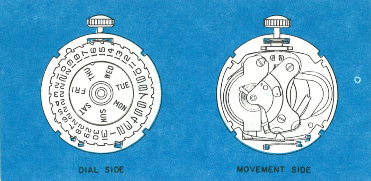
The Timex Model 50 is a 9¾ x 12¾ ligne electronic watch movement. The power to drive the movement is supplied by a miniature energy cell. Power from the energy cell drives the balance, the balance drives the time train which, in turn, rotates the hands.
Electronic, not electric: The difference from the Model 40 is one component. A diode, a semiconductor, has been introduced into the balance wheel circuit to aid amplitude stabilisation. The balance carries the suffix D in the parts list for it.
The hands are set in the normal method, pulling out and rotating the crown. The Model 50 incorporates a device which stops the movement when the crown is in the set position, and in that position the flow of current is interrupted so the cell is not being discharged.
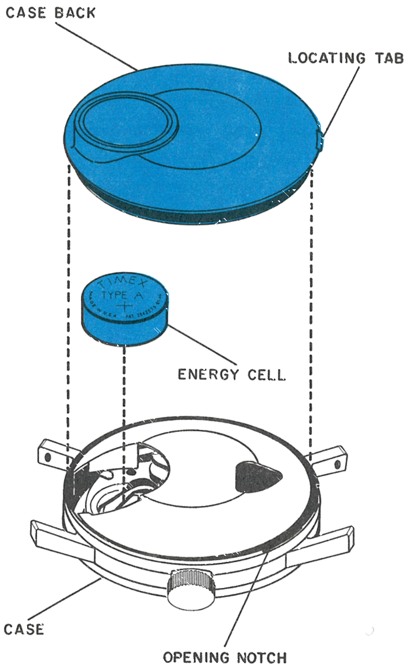
Cells: Use only genuine Timex Energy Cells, Type A. Other types may not deliver the necessary voltage or life and may leak, seriously damaging the movement. An energy cell may explode if disposed of in fire or recharged.
Insert a knife blade in the opening notch on the bezel and snap the caseback off. The locating tab on the caseback is used for orientation of the back during reassembly.
The movement is protected by a movement cover having access for regulation. The energy cell is loose and may be removed for testing. Any cell with a voltage of less than 1.5 volts, or one known to have been in service in excess of one year, should be replaced.
Caution: Avoid short circuiting the cell by metallic connections between the outer case and the negative pole, as this short circuit could shorten the life of the cell.
Fig. 50.3 · Caseback
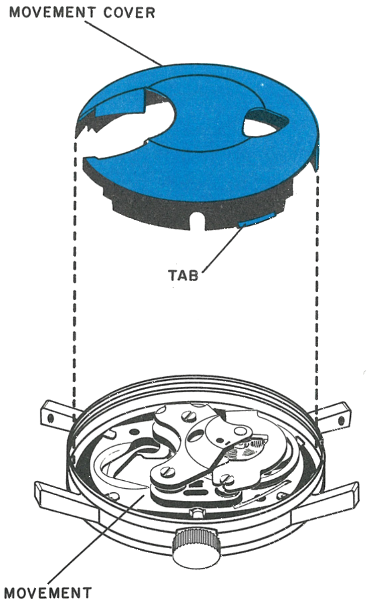
2 · The Movement Cover
The movement cover may now be removed. It is held in place by two tabs which seat in a recess in the bezel. The movement will stay with the bezel, since it can only be removed through the crystal side.
Fig. 50.3 · Movement Cover
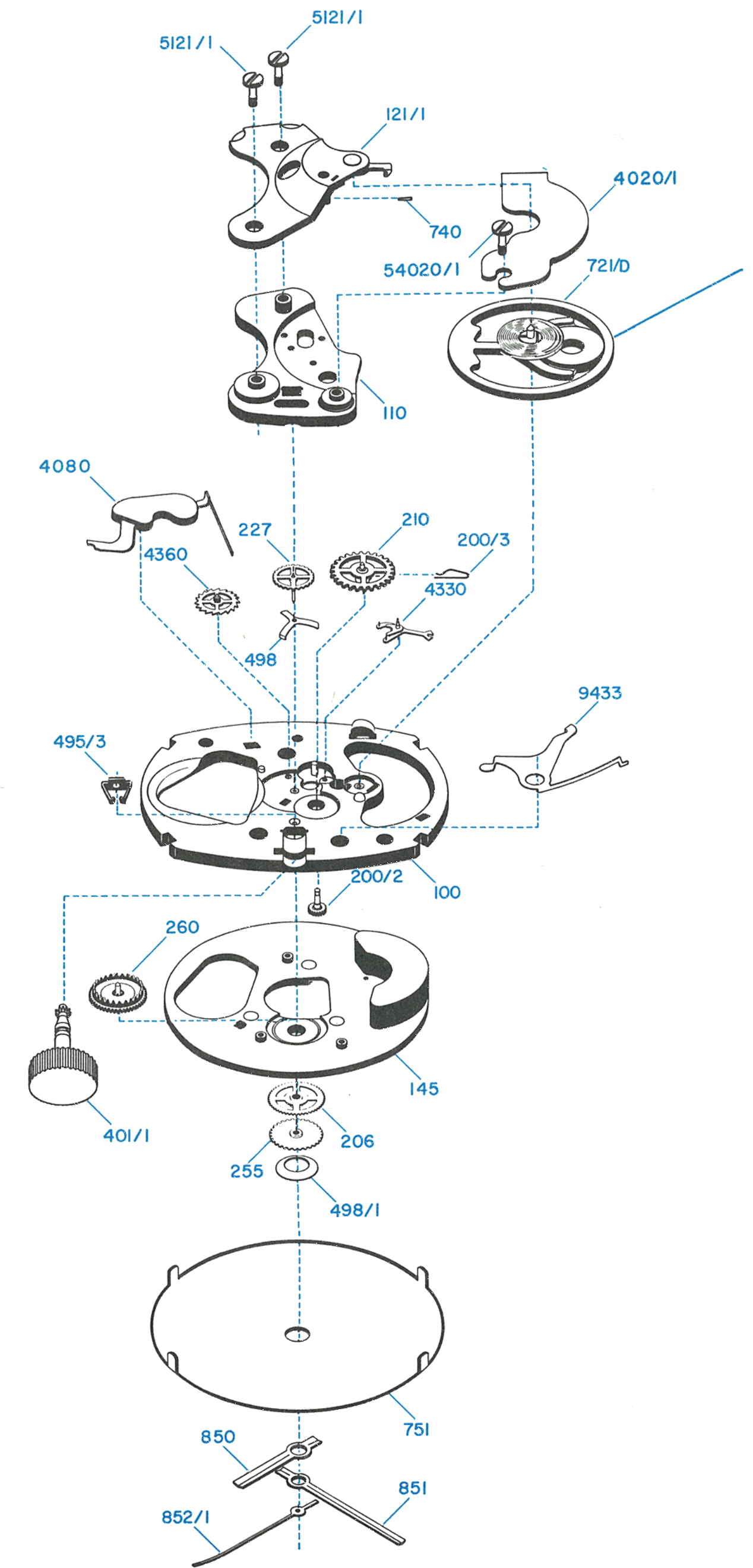
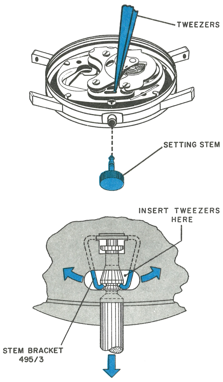
The only function of the stem is to stop the movement and set the hands, so the stem and setting pinion are combined and held by a stem bracket, 495/3. There are no screws or levers.
3 · Releasing the Stem Bracket
Pull the stem into the set position, maintaining a slight outward pull.
Place the points of a heavy set of tweezers into the space between one side of the stem bracket and the stem. Gently release one side of the bracket by pushing the ear of the bracket in the direction of the arrow. The stem will tilt sideways.
Still maintaining the outward pull, repeat the process on the other side. When both sides have been released, the stem will come out completely.
To replace the stem, firmly press it in place with a slight rotating motion so the stem pinion teeth will mesh with the minute wheel teeth.
Fig. 50.4 · Stem Bracket
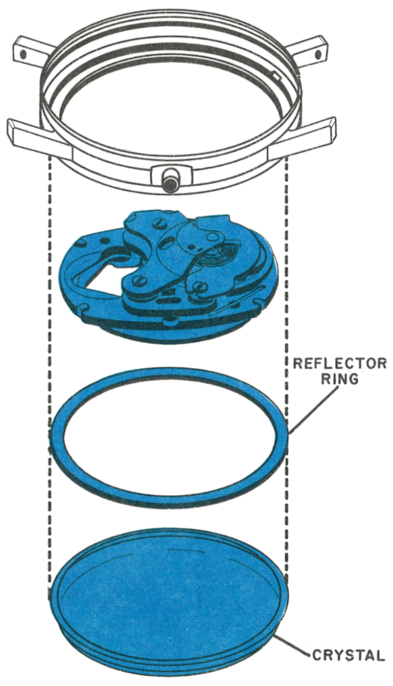
4 · Out Through the Crystal
Remove the crystal using a Timex crystal lift or a conventional crystal lift. The movement and reflector ring can now be removed through the crystal side of the bezel.
Take note of the movement locating tabs in the bezel. When reinserting the movement, be certain it is in its proper position with respect to these tabs, otherwise the reflector ring and crystal will not seat properly.
Fig. 50.4 · Case
5 · The Dial and Hands
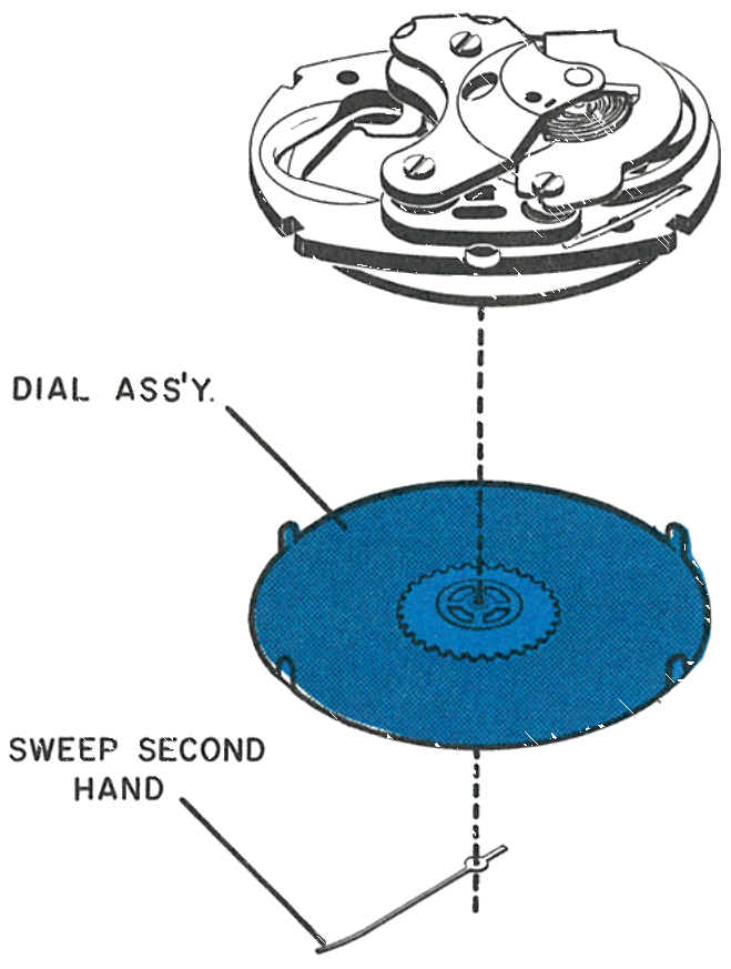
Remove the sweep second hand. The minute and hour hands need not be removed.
Straighten the four tabs on the dial and remove the dial assembly.
Fig. 50.5 · Dial
6 · The Cell Retaining Spring
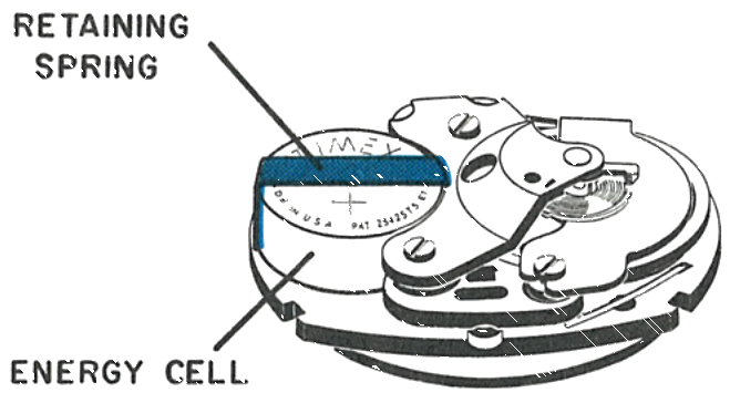
To examine the function of the movement, replace the stem, place the movement on a suitable movement ring and clamp the energy cell in place with an energy cell retaining spring, available on request from a Timex Material Sales Division.
Caution: The negative pole must touch the contact spring assembly (4080); the positive pole is grounded to the movement. Never make a metallic connection between the insulated and uninsulated parts.
Fig. 50.5 · Retaining Spring
7 · How the Cell Sits
Cross section through the retaining spring, energy cell and movement, dial side.
Fig. 50.5 · Section
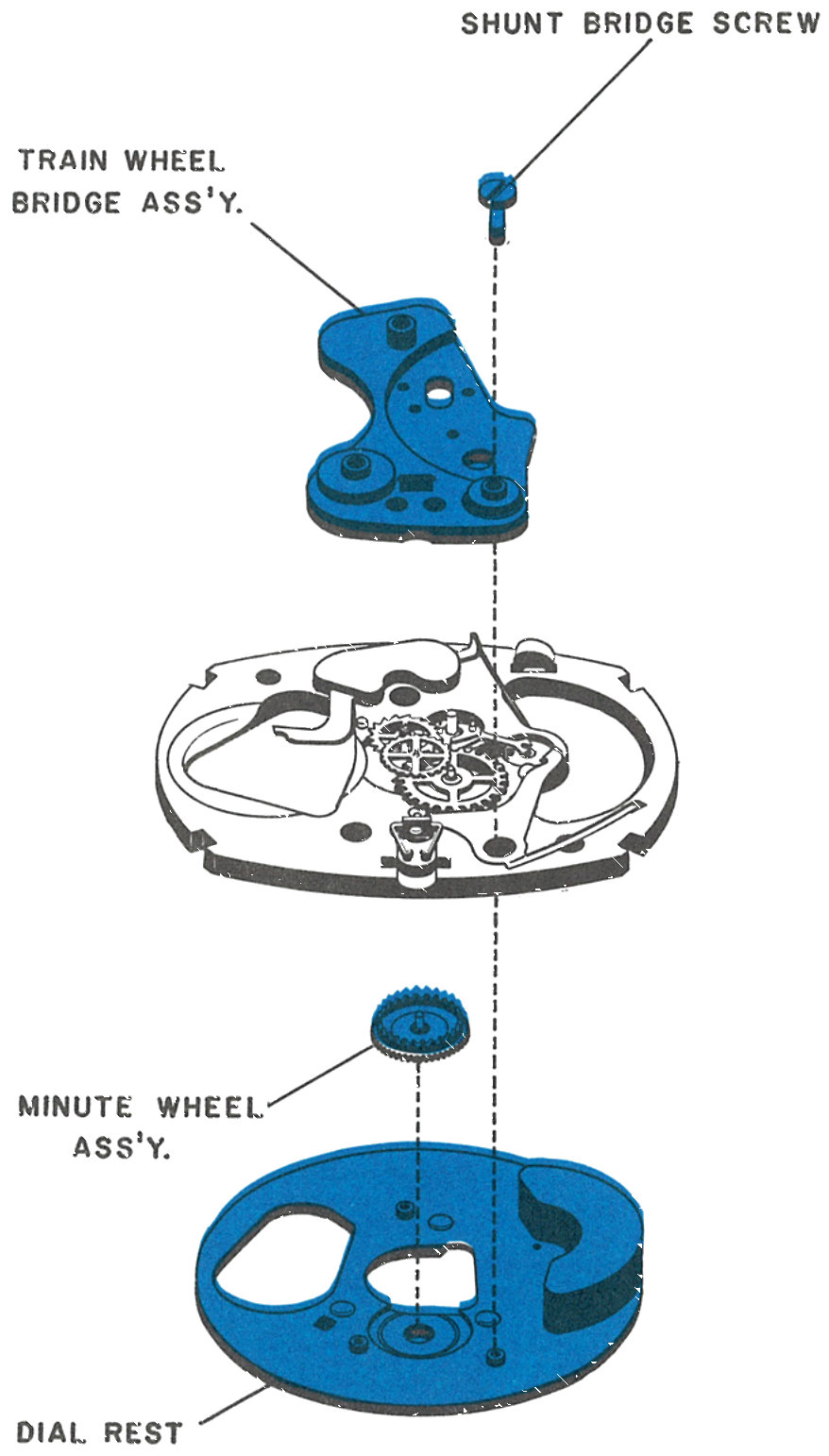
8 · The Shunt Bridge
The energy cell should be removed before proceeding with further disassembly.
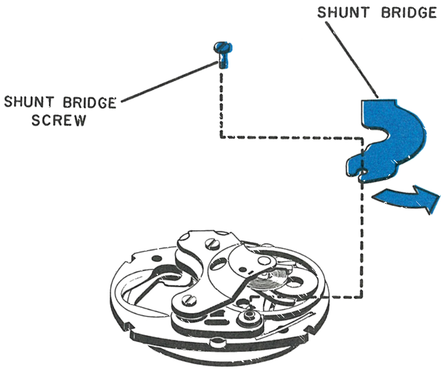
Remove the shunt bridge screw and carefully lift the screw end of the shunt bridge from its post. The opposite end is held in place by a tab overlapping the plate; shifting the screw end slightly to the left will unhook this tab.
Caution: Carry this out carefully so as not to disturb the hairspring or balance. Afterwards put the shunt bridge screw back and tighten it.
Fig. 50.5 · Shunt Bridge
9 · The Balance Bridge
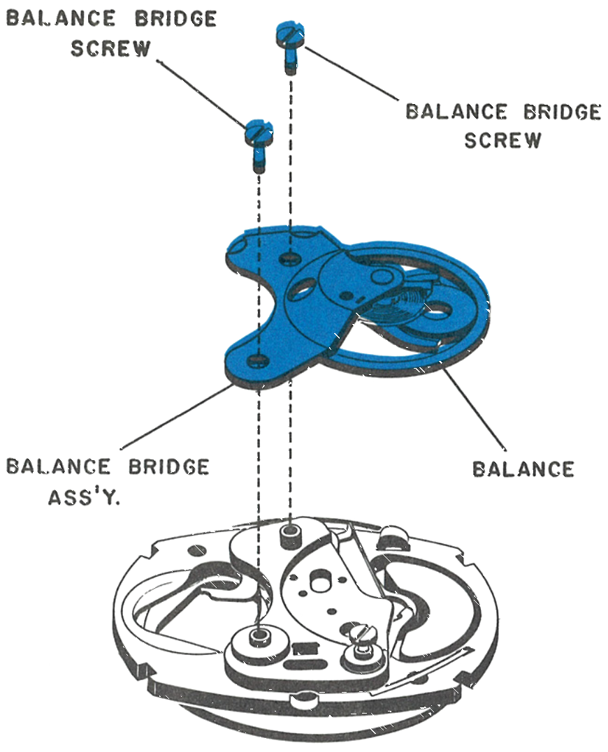
Remove the two balance bridge screws, then the balance bridge assembly and the balance.
Caution: Be certain the shunt bridge screw is in place first, otherwise the train wheel bridge will be disturbed.
Fig. 50.8 · Balance Bridge
10 · The Train Wheel Bridge
Remove the shunt bridge screw. The train wheel bridge and dial rest may now be removed.
Fig. 50.8 · Train Bridge
The Contact & Diode
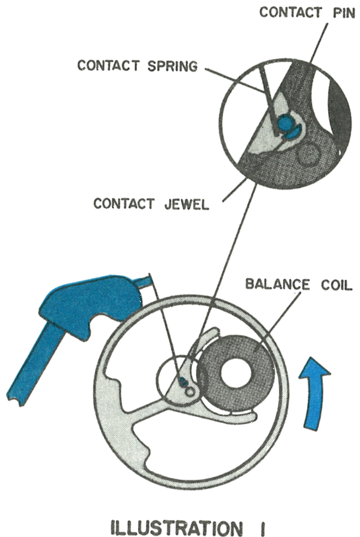
Rotate the balance slowly from its rest position with a clean brush. The instant the contact spring touches the contact pin fixed on the balance, current flows through the balance drive coil. The current induces a magnetic field which opposes the field of the magnet, and this opposition imparts an impulse to the balance when the magnet is in place.
1 · The Contact Closing
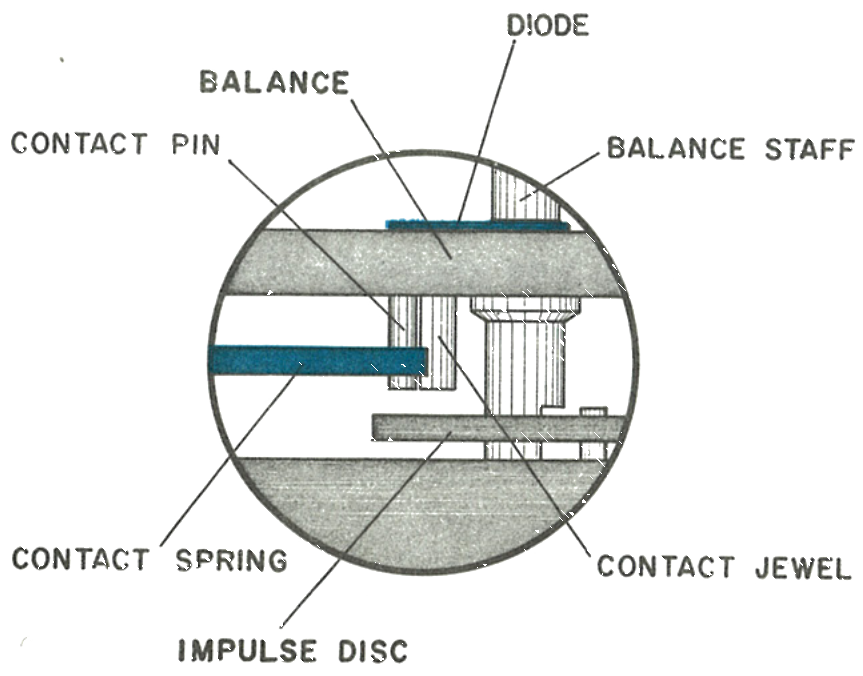
The contact spring, contact pin, contact jewel and balance coil.
Fig. 50.6 · Illustration 1
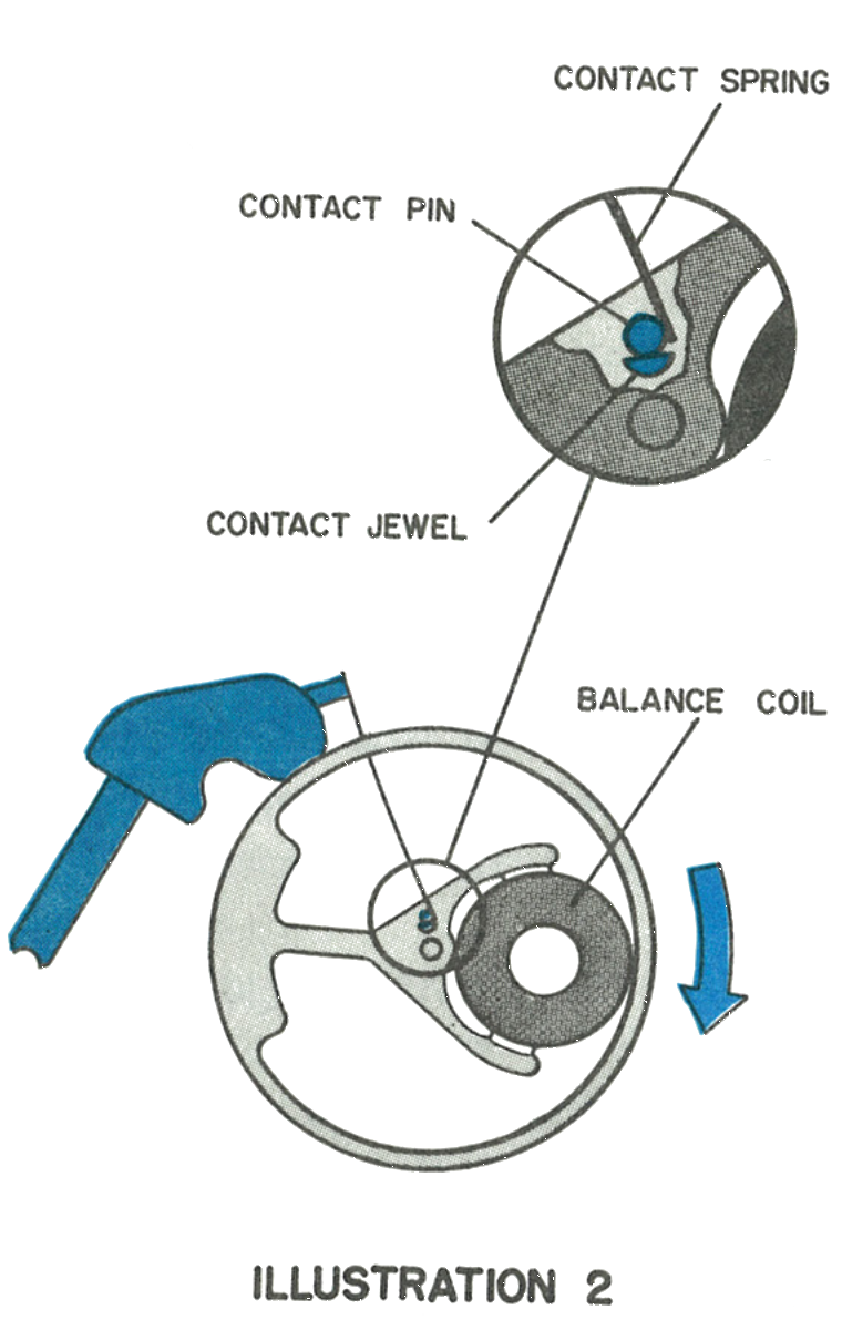
2 · The Return Stroke
After the balance returns to its neutral position the same process is repeated in the opposite direction. Repeat this test several times until the drive action is fully understood. The function of the remainder of the movement is fully mechanical.
Fig. 50.6 · Illustration 2
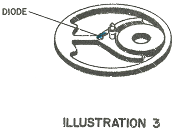
3 · The Diode
The diode, a semiconductor, has been introduced into the balance wheel circuit. Its purpose is to aid in amplitude stabilisation.
The purpose of the contact jewel is to limit the physical contact between the contact pin and contact spring, so that the flow of electrical energy occurs at a precise position during the rotation of the balance.
Fig. 50.6 · Illustration 3
4 · Pointing at the Balance Staff
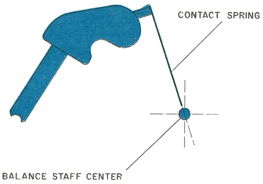
The contact spring must be pointing exactly to the centre of the balance staff.
5 · Centred Between Disc and Balance
It should be centred horizontally between the impulse disc and the balance. The diode is visible on the balance in this section.
Caution: Protect it from scratches and deforming and avoid excessive bending. Do not touch the contact area at the end of the spring. Its length is fixed at the factory.
Fig. 50.7 · Contact Spring
6 · E · Centred Horizontally
It should be centred horizontally between the impulse disc and the balance. The diode is visible in this section.
Fig. 50.7 · Section
Never oil the contact: The contact pin, contact jewel and contact spring must NOT be oiled. Oil would interrupt the flow of current to the drive coil.
Index Train & Stopping
1 · Figures 1 and 2
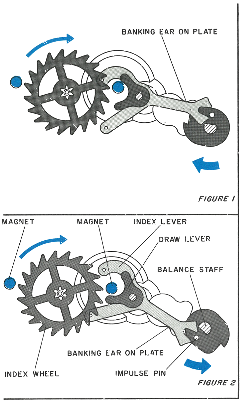
The impulse pin on the balance, when moving clockwise, engages with the fork on the lever and moves the lever counterclockwise. Pin D on the lever engages with the index wheel and moves it forward approximately three quarters of one tooth. The magnets A, B and C attract the tips of the index wheel teeth and move the wheel forward the remaining quarter tooth. Magnet C also attracts the draw lever on the index lever and holds the index lever in place.
If, for any reason, the index wheel is not positioned correctly by the magnets, pin E on the lever turns the index wheel to its correct position, so that the next engagement of pin D will advance the index wheel correctly.
Fig. 50.9 · Figures 1 and 2
2 · The Friction Pinion
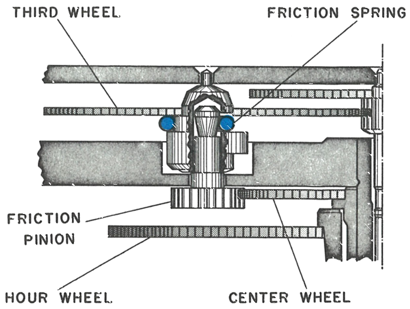
Setting friction for the dial train is provided by a spring connecting the friction pinion and the third wheel. The third wheel and friction pinion may be separated by lifting the friction pinion with tweezers, which unsnaps it from the friction spring. To reassemble, press the pinion firmly back into place. It is not necessary to remove the friction spring from the third wheel.
3 · The Stop Mechanism
The balance stop mechanism is purely mechanical.
Fig. 50.9 · Friction Pinion
The balance stop mechanism is purely mechanical.
4 · Running Position
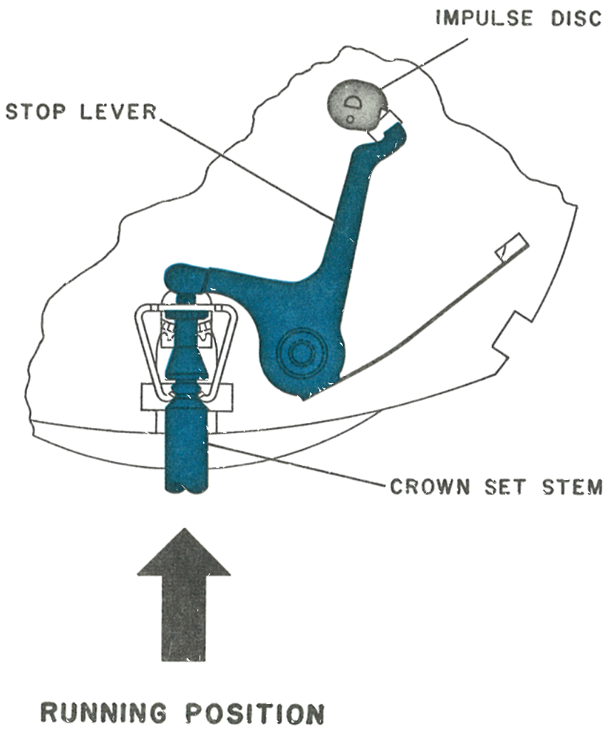
The tip of the stem butts against the stop lever and keeps the tip of the stop lever away from the balance impulse disc.
Fig. 50.10 · Running
5 · Stop Position
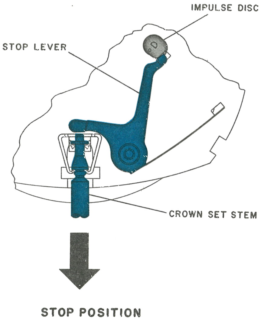
With the stem pulled out into the set position, the tip of the stop lever butts against the impulse disc on the balance, stopping the balance.
Fig. 50.10 · Stop
6 · The Seconds Wheel Friction Washer
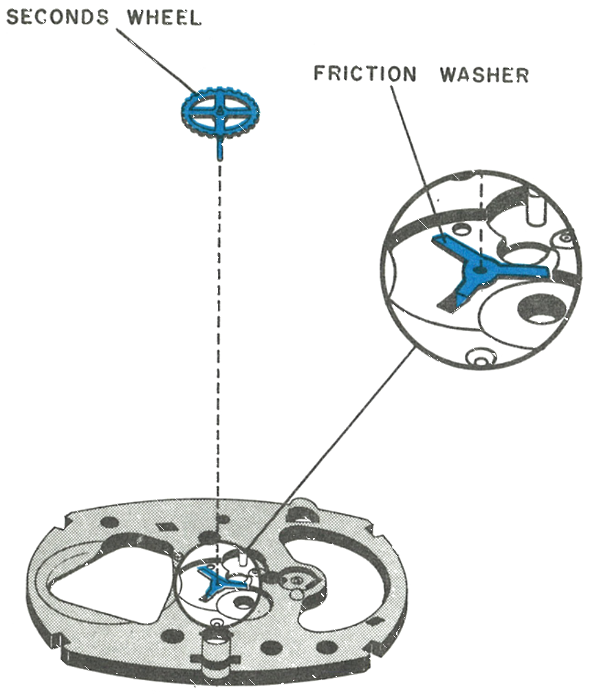
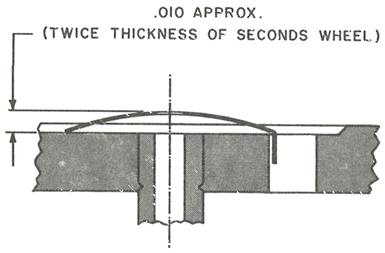
A friction washer is located between the plate and the seconds wheel, domed slightly. Check that it has not become damaged during disassembly. Too much friction will cause too great a drag on the movement; too little will cause an erratic sweep second hand action.
A tab on one leg of the washer fits into a slot on the plate to prevent it from turning.
Fig. 50.11 · Friction Washer
7 · The Dome
The dome is .010 approximately, twice the thickness of the seconds wheel.
Fig. 50.11 · Washer Dome
Cleaning & Lubrication
Lubricant change, June 1974: Timex Service Bulletin No. 111 replaced the factory oil for this model. Moebius Synt-A-Lube oil is used instead of Elgin M56B oil. (It supersedes Bulletin No. 108.)
Timex has found, after careful investigation, that the best way to clean the movement is to disassemble it only to the point of removing the balance bridge and the balance.
The balance should be cleaned separately in a small jar to avoid damage to the coil. The coil is composed of ultra-fine copper wire and should not be handled with tweezers or other sharp instruments. Only standard watch cleaning solutions should be used throughout. Particles adhering to the magnet can be removed with Scotch tape.
The movement should be re-lubricated in the normal manner using only high grade watch oils; Elgin M56b is used in factory assembly. The balance bearings should be filled half full before inserting the balance.
Other points: the impulse pin or fork slot, the index lever pivots, the index wheel teeth, all wheel pivots, the junction of the center wheel pinion and friction washer, and the junction between the minute wheel and dial rest. Apply grease, Hamilton PML type, to the stem where it is held by the stem bracket.
Caution: Do not lubricate the contact spring or contact pin on the balance. Do not use oil or greases containing silicone. Since the watch contains permanent magnets, no attempt should be made to demagnetize it.
Reassembly
1 · Third wheel2 · Friction washer3 · Index lever4 · Index wheel5 · Seconds wheel6 · The Stem
Since the only function of the stem in the Model 50 is to stop the movement and set the hands, the stem retention has been simplified by combining the stem and setting pinion and providing a novel stem bracket, 495/3. There are no screws or levers holding the stem.
The third wheel: Place the friction pinion, pinion side down, on a flat anvil, then place the movement plate over it, then snap the third wheel with its friction spring over the post. This avoids damage to the hole in the movement plate.
10 · Balance Endshake
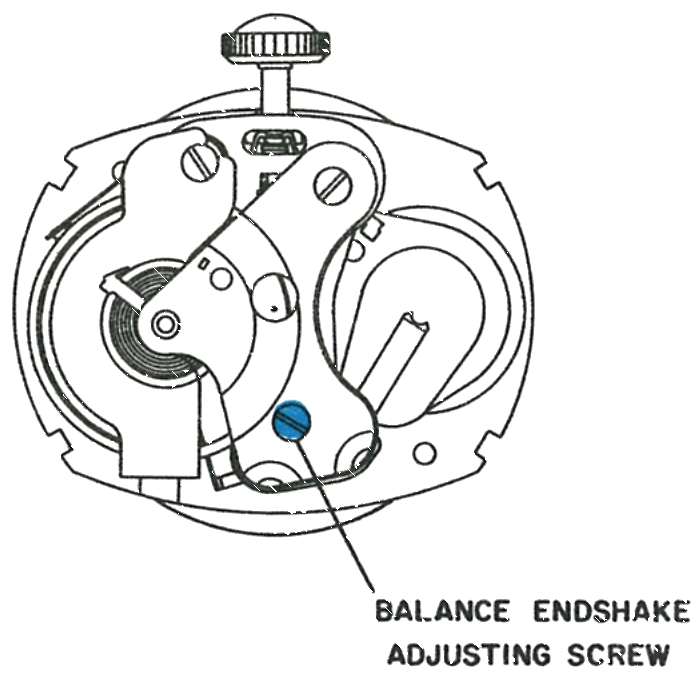
The balance bridge screw on the 9 o’clock side serves to adjust the balance endshake. Tightening this screw will reduce the endshake. Use caution while adjusting to avoid damage to the points of the balance staff.
Fig. 50.13 · Endshake
11 · The Hairspring and Regulator
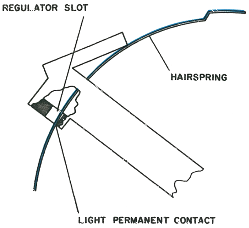
Inspect the hairspring to be certain it is properly adjusted. The hairspring should be in light permanent contact with the inside edge of the regulator slot, and is held in this position by a tab extending from the regulator.
Fig. 50.13 · Regulator
12 · The Sweep Second Hand
When replacing the dial assembly, pre-position the hands to 12:00 before inserting the tabs on the dial into the plate, then bend the tabs to secure the dial.
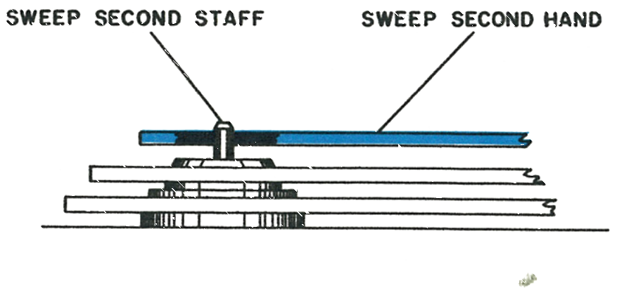
Replace the sweep second hand by driving it just below the end of the sweep second staff. Be certain the sweep hand is set below the chamfer on the top of the staff.
Fig. 50.13 · Sweep Hand
This guide is based on the original Timex factory service manual for the Model 50 movement.