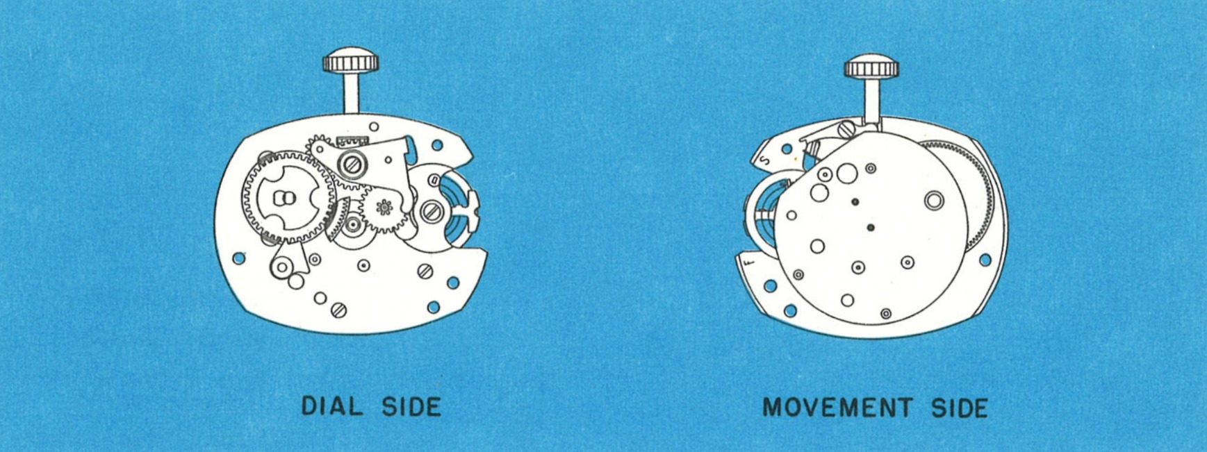
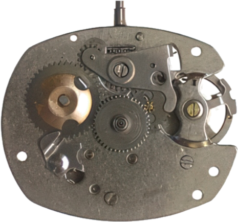
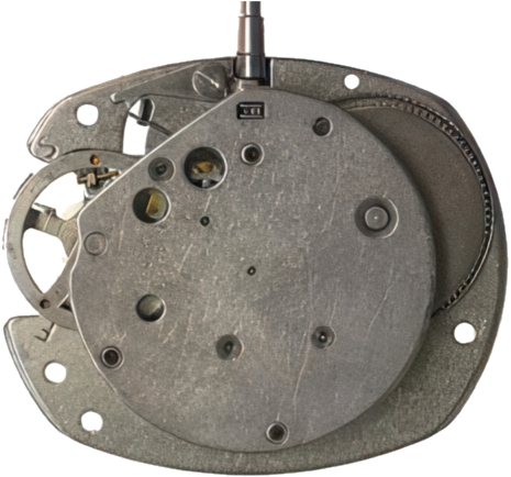
The TIMEX Model 24 is an 11¼ × 9¼ ligne movement featuring the proprietary "V-Conic" bearing system and a rugged two-plate design. Distinguished by its round movement plate, it uses full plates instead of bridges, ensuring complete interchangeability of the escapement and gear train without selective fitting.
MechanicalTwo-PlateV-Conic Bearings
Factory Service Manual · Fig. 24.1 · Dial Side & Movement Side
Size (Ligne)9¼ × 11¼
Size (mm)21.08 × 25.35 mm
TypeMechanical · Hand-wind
Plate DesignTwo Full Plates
BearingsV-Conic (proprietary)
Lubricant (factory)Elgin M56b
MainspringDo NOT oil
V-conic fillno less than ¾ full
Height4.10 mm
Jewels0
EscapementPin lever
Beat rate18,000 bph
Power reserve42 h
Height, jewels, escapement, beat rate and power reserve: ranfft.org
The Model 24 Movement
The TIMEX Model 24 is an 11¼′′′ × 9¼′′′ movement featuring the “V-conic” bearings system and a rugged two-plate design. It is readily distinguished from other TIMEX models by the round movement plate.
Whereas most watches utilise bridges, TIMEX has constructed this movement with full plates, to take advantage of the accuracy inherent in this type of design. This ensures complete interchangeability for the escapement and gear train, without selective fitting or adjustment.
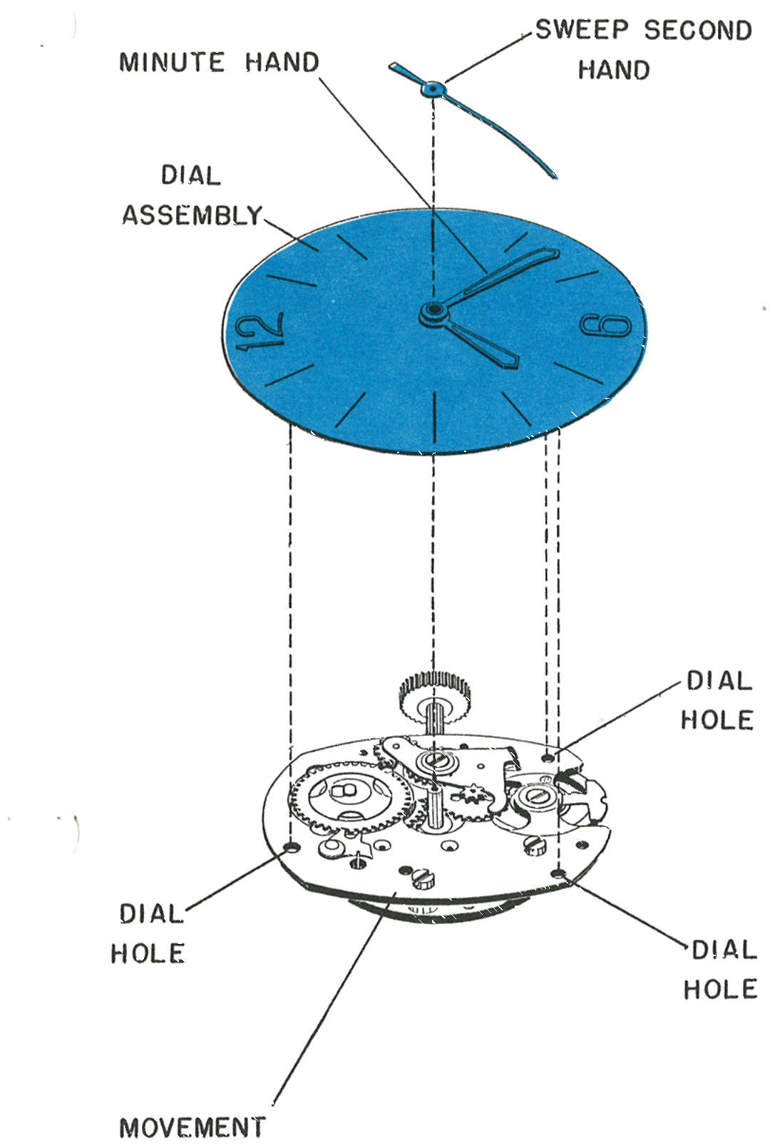
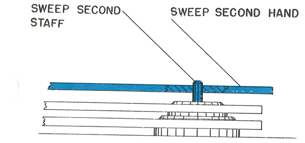
Remove the sweep second hand. Do not remove the minute or hour hand at this stage.
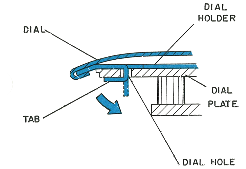
The dial holder clamps the dial to the movement by means of three tabs bent through dial holes, onto the dial plate. Flex the tabs gently outward to release the dial assembly.
Once the dial is off the movement, there is no need to disassemble the dial assembly further for cleaning unless severe contamination is present on the friction and cannon pinions. Removing the minute hand will free the friction pinion, which is held in the cannon pinion by a snap fit.
The dial holder is held on the movement by three tabs bent through dial holes onto the dial plate. On some models a dial holder is not used; there, three tabs are formed on the dial itself and used in the same manner.
Fig. 24.3 · Dial & hands
Fig. 24.3 · Dial holder & tab
2 · Removing the Ratchet Wheel
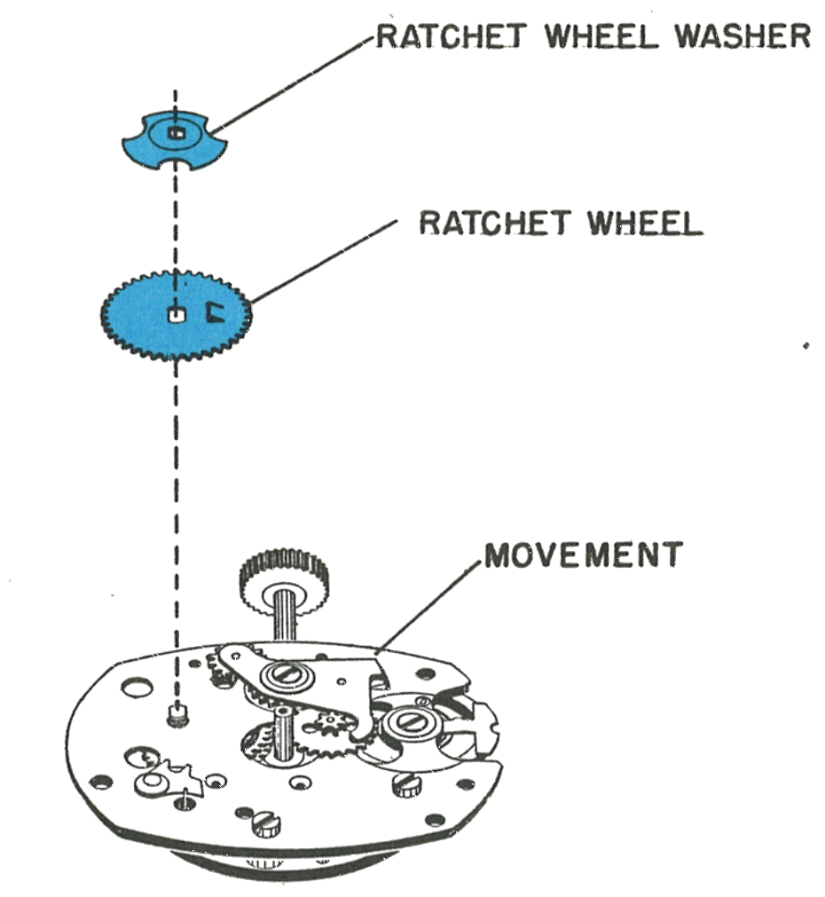
Grasp the crown in the fingers of one hand and release the click by holding it away from the ratchet wheel. Let the crown revolve slowly in the fingers, being careful not to let the crown slip. This releases the mainspring tension safely.
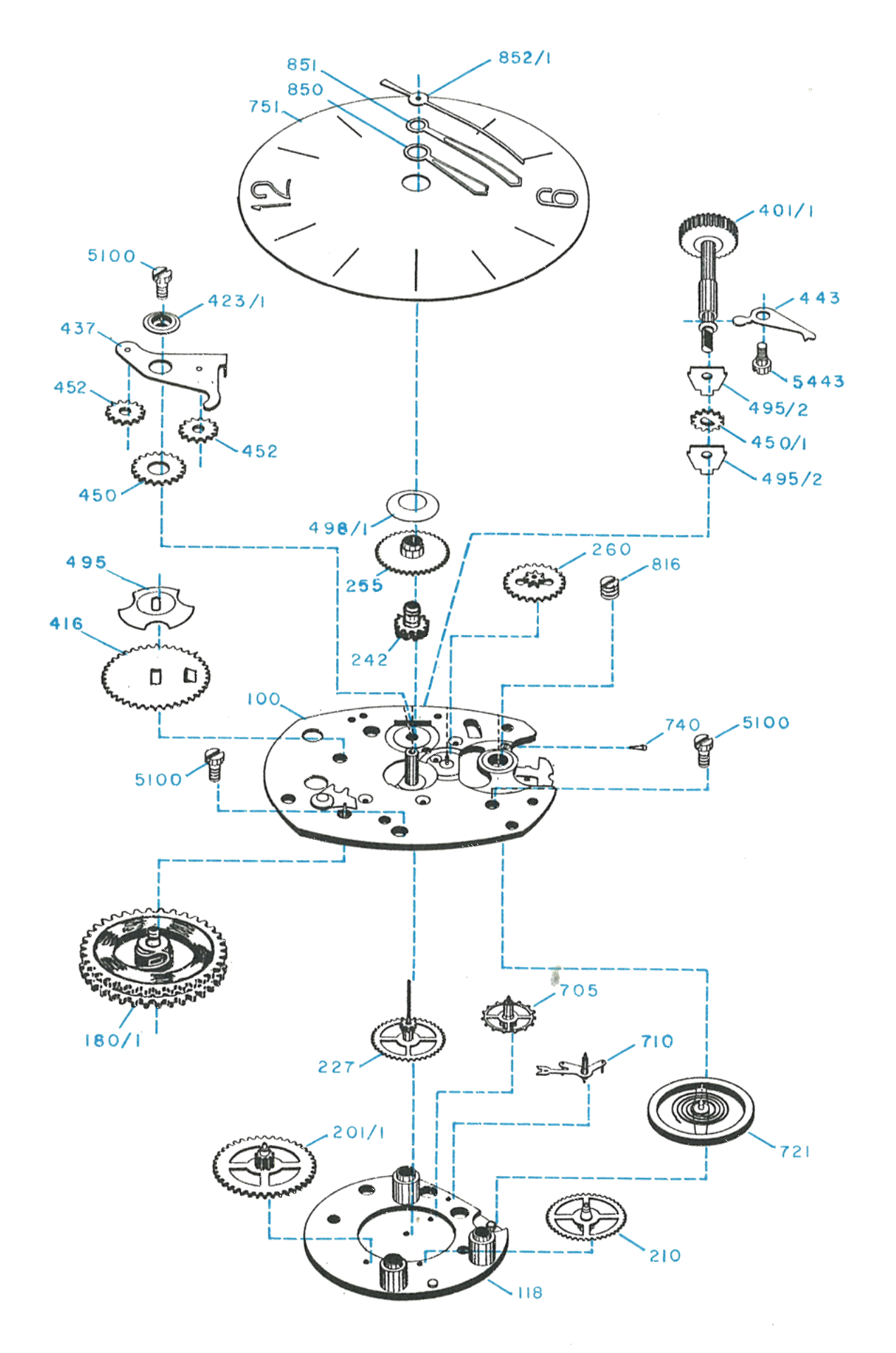
When the mainspring has been fully let down, remove the ratchet wheel washer (ref. 495) and ratchet wheel (ref. 416).
3 · Removing the Crown and Stem
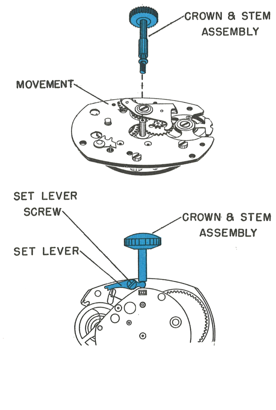
Invert the movement so that the movement plate is facing you.
Locate the set lever screw (ref. 5443). Turn it approximately one turn, just enough to lift the tail of the set lever out of engagement with the stem.
The crown and stem assembly (ref. 401/1) can now be withdrawn from the movement.
Fig. 24.4 · Ratchet wheel
Fig. 24.4 · Crown & stem
4 · Removing the Balance
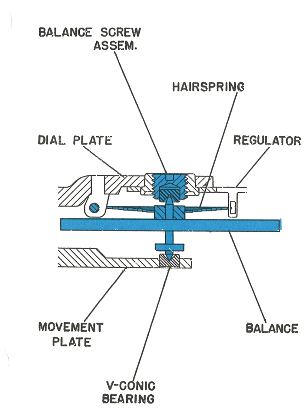
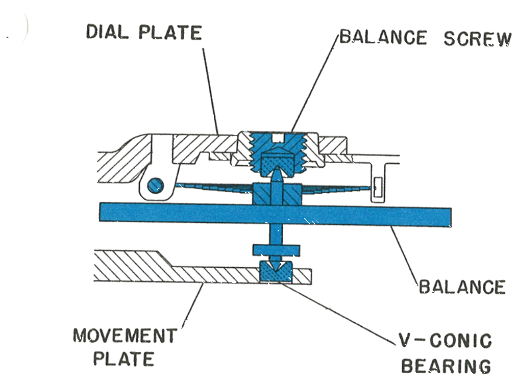
Two "V-conic" bearings are used as bearings for the balance staff on the TIMEX Model 24 movement. The bearing on the dial plate is driven into a screw so that fine endshake adjustment is possible.
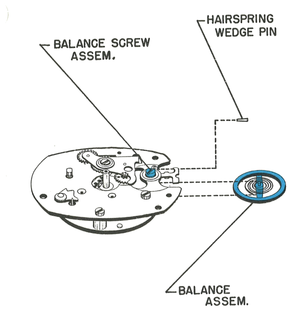
Remove the hairspring wedge pin (ref. 740), being careful not to distort either the pin or the hairspring.
Rotate the balance slowly until the hairspring tail is free of the hairspring wedge pin bracket and the regulator.
Loosen the balance screw assembly (ref. 816) in the counterclockwise direction using a suitable screwdriver, until the end of the balance staff is free of the "V-conic" bearing. During loosening, apply only minimum downward pressure with the screwdriver. Excessive downward pressure could seriously damage the balance staff points.
Carefully remove the balance assembly (ref. 721).
The balance screw assembly and hairspring wedge pin seen in place on the movement, with the balance assembly alongside.
Fig. 24.5 · Balance assembly
Fig. 24.5 · V-Conic bearing
Cleaning & Lubrication
Lubricant change, June 1974: Timex Service Bulletin No. 111 replaced the factory oil for this model. Moebius Synt-A-Lube oil is used instead of Elgin M56B oil or Tenneco #415 oil. (It supersedes Bulletin No. 108.)
1 · Cleaning the Movement
If a cleaning machine is used, place the movement in the basket with the dial plate down to ensure proper drainage of fluid from the mainspring barrel. Swirl well in the cleaning fluid, then pass through two sets of rinsing fluid. The final cleaning fluid must be absolutely clean. After cleaning, dry the movement thoroughly.
If a cleaning machine is not available, re-insert the stem and grasp the movement firmly around the stem. Shake it in the cleaning and rinsing fluids to ensure the fluid passes through the entire mechanism.
The balance assembly should be cleaned separately in a small jar to prevent damage to the hairspring. Use only standard watch cleaning solutions throughout.
Caution: Do not oil the mainspring. It is permanently lubricated with a solid coating which is not affected by normal cleaning solutions.
2 · Lubricating the Movement
Re-oil the movement in the normal manner using only high grade watch oils. The oil used in factory assembly is Elgin M56b. A modern equivalent such as Moebius 9010 is a common substitute today, though the manual itself names only the Elgin oil.
Mainspring (ref. 180/1). Permanently lubricated with a solid coating. Do not oil the mainspring. Cleaning solutions do not affect this coating.
Escape Wheel Upper Pivot. Oil through the holes in the minute wheel.
"V-conic" Bearings. Fill no less than ¾ full before replacing the balance assembly.
Wind & Set Train. Oil both the top and bottom sides of the intermediate wind pinion and wind and set pinions.
Reassembly
Tilt the balance wheel and insert the dial side pivot first, then lower the movement side pivot into the "V-conic" bearing. Adjust the balance screw just enough to hold the balance in place. Do not fully tighten yet.
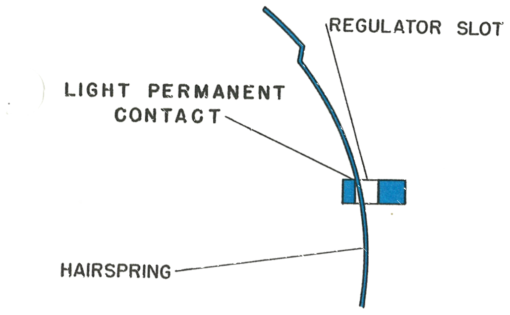
Rotate the balance and insert the hairspring into the regulator slot and hairspring wedge pin bracket. Before repinning, confirm the impulse pin is within the slot on the fork. Re-pin the hairspring ensuring the wedge pin is straight and true. Any distortion to the pin could interfere with the normal "breathing" of the hairspring.
Adjust the endshake using the balance screw assembly, applying only minimum downward pressure. Excessive downward pressure on the balance screw will damage the points of the balance staff.
The hairspring should be in light permanent contact with the inside edge of the regulator slot. It should not leave the inside edge of the regulator slot during any part of its amplitude.
Set the hour and minute hands to 12:00 before bending the tabs on the dial holder to secure the dial. Important: if the minute hand was removed, replace it on the dial assembly together with the friction and cannon pinions before placing the dial assembly on the movement.
Drive the sweep second hand just below the chamfer on the top of the sweep second staff. The hand should seat firmly but not be forced past the chamfer line.
Fig. 24.7 · Replacing the balance
Fig. 24.7 · Hairspring & regulator slot
Fig. 24.7 · Sweep second hand
Hands set to12:00
V-cone fill≥ ¾ full
This guide is based on the original Timex factory service manual for the Model 24 movement.