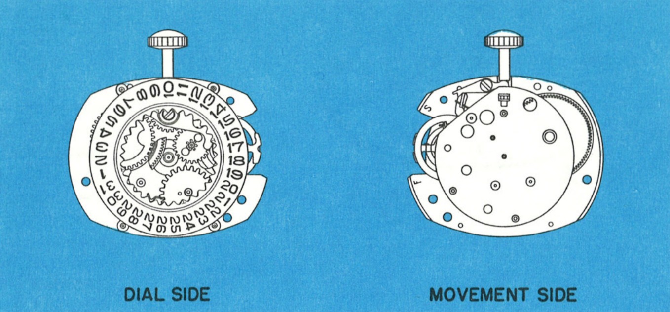
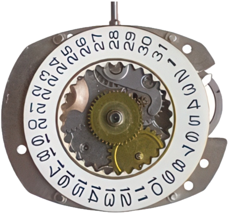
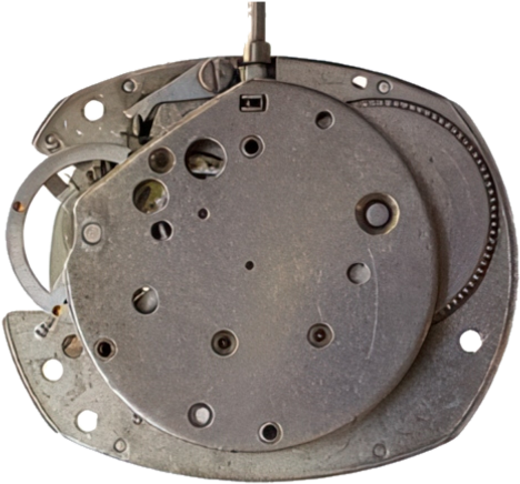
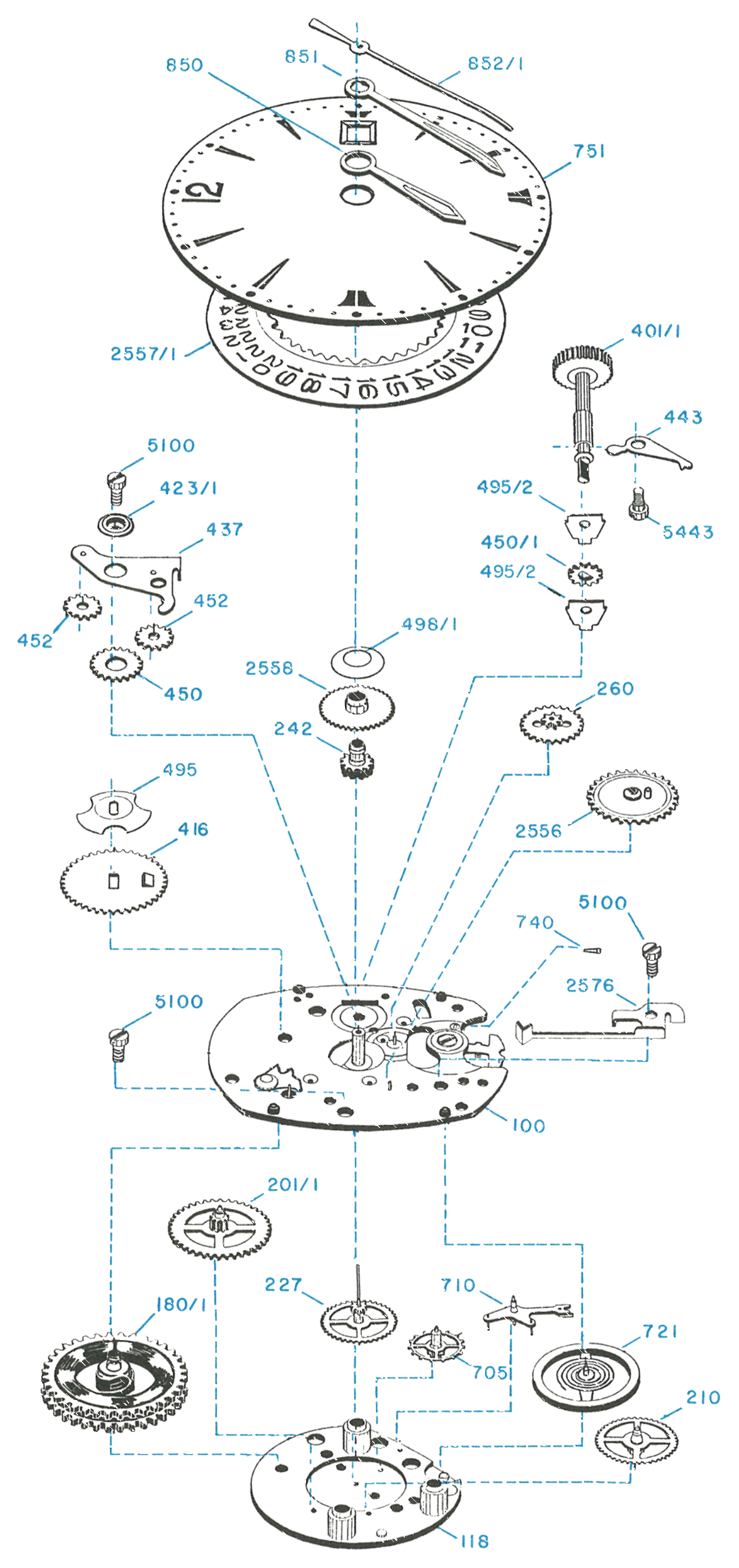
A calendar movement built on the construction of the Model 24, with the same V-Conic bearing system and two plate design. The entire calendar mechanism is housed between the dial plate and the dial.
Hand-woundCalendarV-ConicModel 24 Base
Factory Service Manual · Model 25 · Dial Side & Movement Side
Ligne9¼ by 11¼
Diameter21.08 by 25.35 mm
Diameter (inches).998 by .830 in
TypeHand-wound calendar
BearingsV-Conic
Built onModel 24 construction
ManualService Manual · Model 25
Height4.40 mm
Jewels0
EscapementPin lever
Beat rate18,000 bph
Power reserve42 h
Height, jewels, escapement, beat rate and power reserve: ranfft.org
A Calendar on Model 24 Bones
The Timex Model 25 is an 11¼‴ x 9¼‴ calendar movement utilizing the basic construction of the Model 24. Like the Model 24 it features a V-Conic bearing system and rugged two plate design. The entire calendar mechanism is efficiently housed between the dial plate and dial.
Whereas most watches utilize bridges, Timex constructed the Model 25 movement with full plates to take advantage of the accuracy inherent in this type of design. This accuracy insures complete interchangeability for the escapement and gear train without the need for selective fitting and adjustments which complicate the repair of most watches.
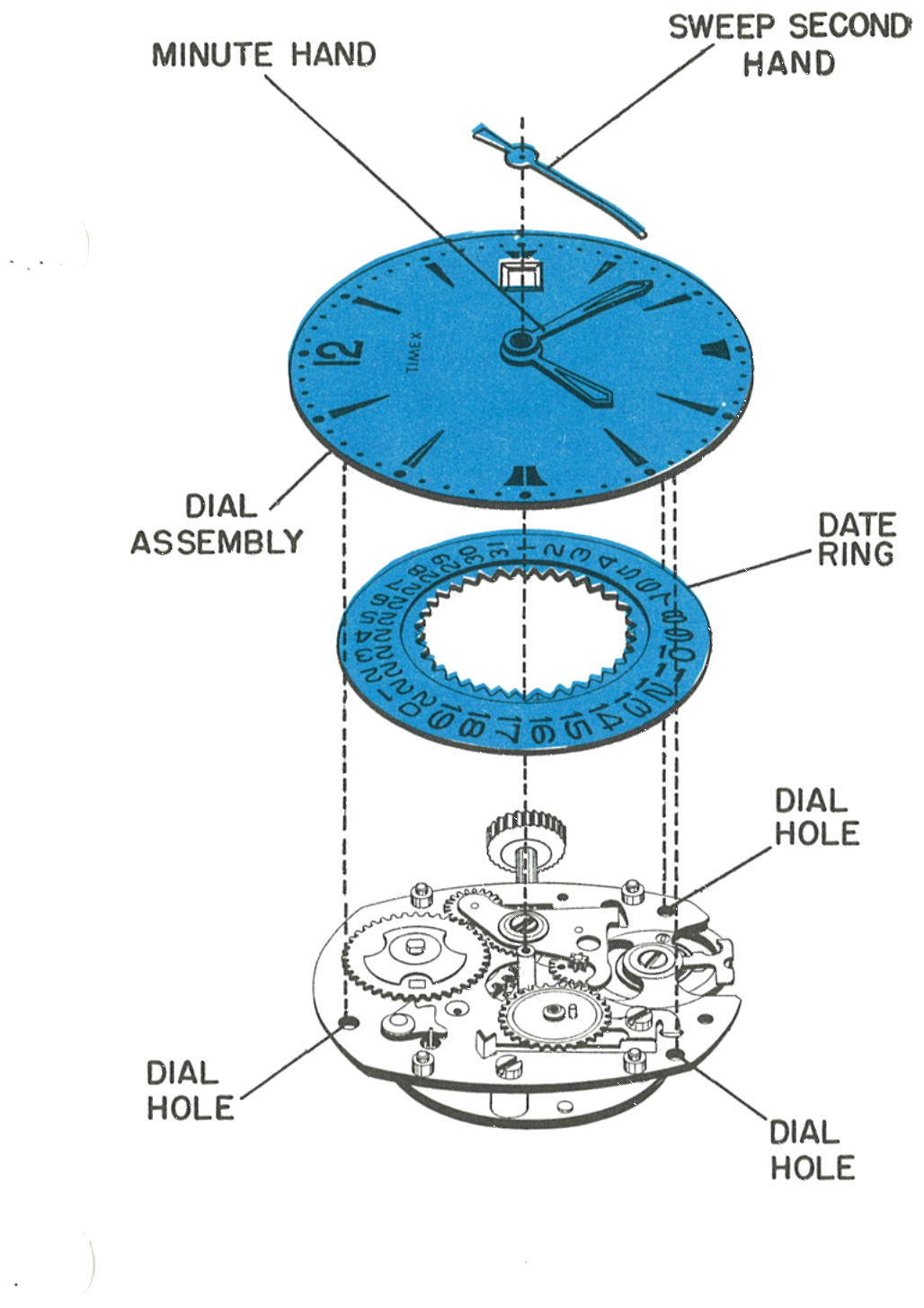
Timex found through long and careful research that the best method of cleaning is with only the sweep second hand, dial, date ring, date wheel assembly, ratchet wheel and balance removed. The cleaning fluid, while removing any contamination from the movement, will also remove oil from the gear train, pivots and holes.
Note: If further dismantling is required, removal of the movement plate will expose the gear train and associated parts. Reassembly should start with the dial plate.
Remove the sweep second hand. Do not remove the minute or hour hand.
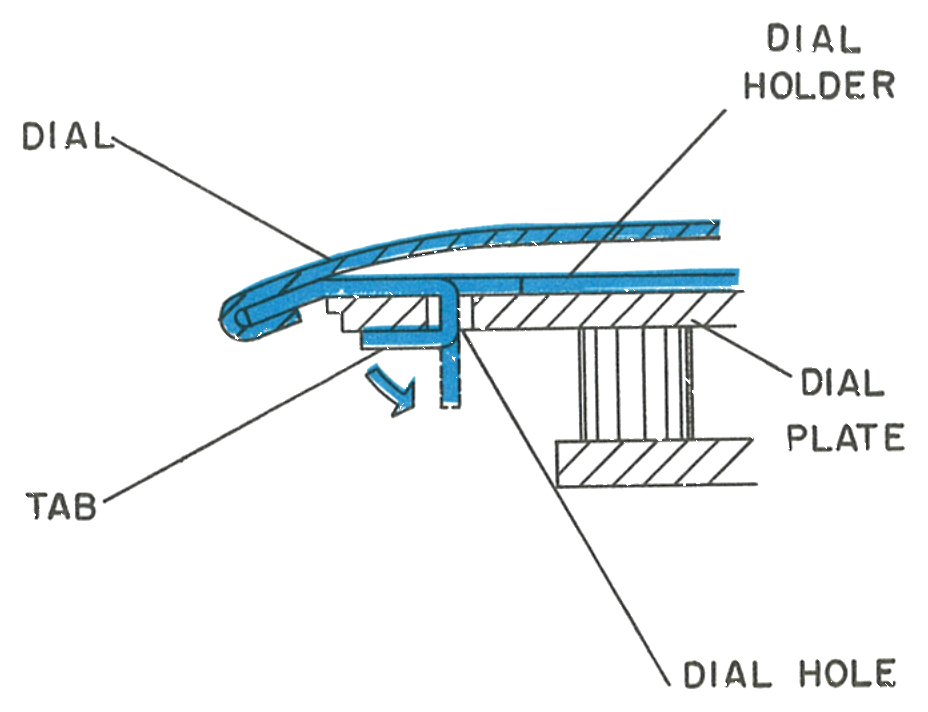
The dial holder, to which the dial is clamped, is held on the movement by means of three tabs which are bent through dial holes onto the dial plate.
Once the dial is off the movement, the date ring can be removed. There is no need for further disassembly of the dial assembly for cleaning unless severe contamination is present on the friction and cannon pinions. Should further disassembly be necessary, removal of the minute hand will free the friction and cannon pinion assembly. The friction pinion is held in the cannon pinion by a snap fit.
Fig. 25.3 · Dial, date ring & hands
2 · The Dial Holder Tabs
The three tabs on the dial holder are bent through the dial holes onto the dial plate. Straighten them to release the dial assembly.
Fig. 25.3 · Dial holder & tab
3 · Removing the Date Wheel and Ratchet Wheel
Grasp the crown with the fingers of one hand and release the click by holding the click away from the ratchet wheel. Let the crown revolve slowly in the fingers, being careful not to let the crown slip.
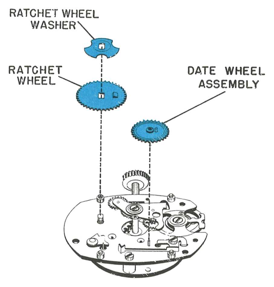
When the mainspring has been fully let down, remove the ratchet wheel washer and ratchet wheel.
Note: To remove the ratchet wheel washer, lift one side free of the lancing in the ratchet wheel and revolve the washer approximately ¼ turn.
Fig. 25.4 · Date wheel & ratchet wheel
4 · Removing the Crown and Stem
Invert the movement so that the movement plate is facing you.
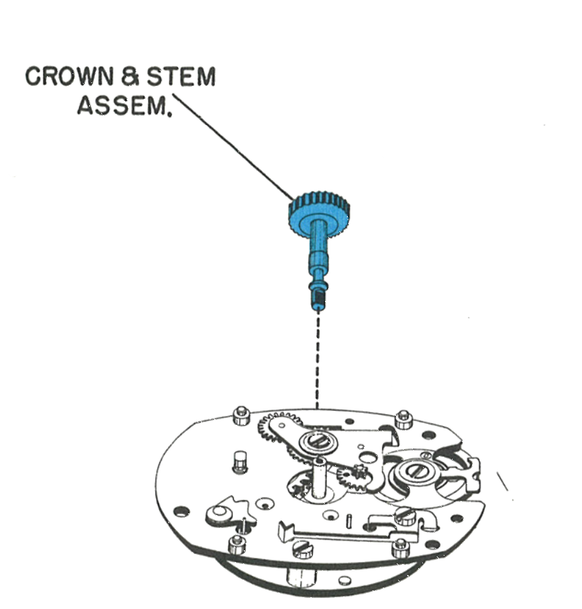
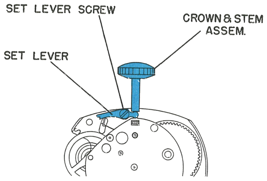
Turn the set lever screw approximately one turn and lift the tail of the set lever out of engagement with the stem. The crown and stem can now be removed.
Fig. 25.4 · Crown & stem
5 · The Set Lever
The set lever screw and set lever, seen on the movement plate side. Turning the screw about one turn frees the tail of the set lever from the stem.
Fig. 25.4 · Set lever
6 · Removing the Balance Wheel
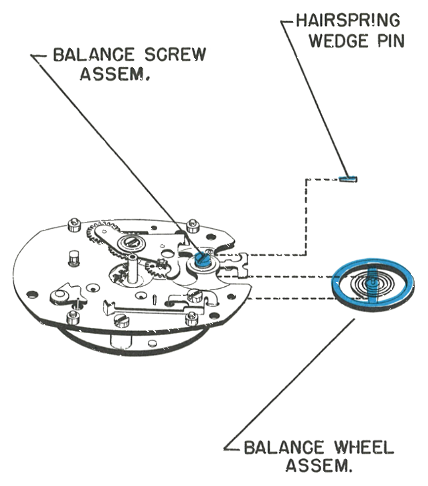
Remove the hairspring wedge pin, being careful not to distort either the pin or the hairspring.
Rotate the balance wheel slowly until the hairspring tail is free of the hairspring wedge pin bracket and the regulator.
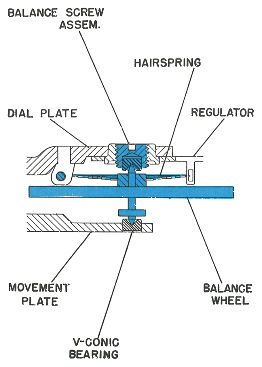
Loosen the balance screw assembly, counter-clockwise, using a suitable screw driver until the end of the balance staff is free of the V-Conic bearing.
Caution: Only minimum downward pressure should be applied with the screw driver. Excessive downward pressure could seriously damage the balance staff points.
Fig. 25.5 · Removing the balance
7 · The V-Conic Bearing
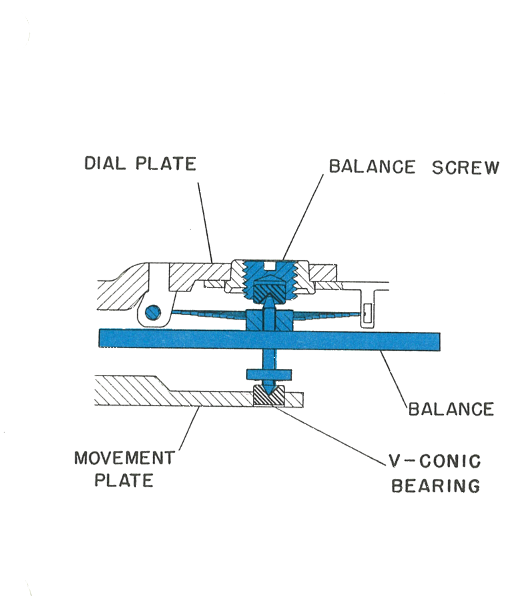
Two V-Conic studs are used as bearings for the balance staff. The bearing on the dial plate is mounted in a screw so that fine endshake adjustment is possible.
Fig. 25.5 · V-Conic bearing
Cleaning & Lubrication
Lubricant change, June 1974: Timex Service Bulletin No. 111 replaced the factory oil for this model. Moebius Synt-A-Lube oil is used instead of Elgin M56B oil or Tenneco #415 oil. (It supersedes Bulletin No. 108.)
If a cleaning machine is not available, the same procedure should be followed manually, by reinserting the stem into the movement, grasping the movement firmly around the stem and shaking it in the cleaning and rinsing fluids to insure that the fluid will pass through the entire mechanism. The balance assembly should be cleaned separately in a small jar to prevent damage to the hairspring. Only standard watch cleaning solutions should be used throughout.
If a cleaning machine is used, place the movement in the basket with the dial plate down to insure proper drainage of the fluid from the mainspring barrel. It should be well swirled in the cleaning fluid, after which two sets of rinsing fluid should be used. The final cleaning fluid must be absolutely clean, and the movement thoroughly dried afterwards.
The balance assembly should be cleaned separately in a small jar to prevent damage to the hairspring. Only standard watch cleaning solutions should be used throughout.
The movement should be reoiled in the normal manner using only high grade watch oils; the oil used in factory assembly is Elgin M56b. The upper pivot of the escape wheel can be oiled through the holes in the minute wheel. The V-Conic bearings should be oiled ½ to ¾ full before replacing the balance wheel. Oil both the top and bottom sides of the intermediate wind pinion and the wind and set pinions, and the intersection of the rocking bar and set lever. A slot has been provided at the base of the centre post to facilitate oiling the fourth pinion upper pivot. If the friction pinion has been removed from the cannon pinion and cleaned, oil it before reassembly; the impulse pin should be oiled at its working surface. Rubber gaskets used on crowns, such as those on waterproof and dustproof models, should be lubricated with silicone grease or silicone oil.
Caution: The mainspring is permanently lubricated with a solid coating which is not affected by normal cleaning solutions and should not be oiled.
Reassembly
1 · Replacing the Balance Wheel
Replace the balance wheel carefully into the movement by tilting the wheel and inserting first the dial side pivot, the hairspring side, then the movement side pivot into the V-Conic bearing. Adjust the balance screw enough to hold the balance in place.
By rotating the balance wheel, insert the hairspring into the regulator slot and hairspring wedge pin bracket. Before repinning the hairspring, make certain the impulse pin is within the slot in the fork of the pallet lever.
Repin the hairspring, making sure that the wedge pin is straight and true, as any distortion to the pin could interfere with the normal breathing of the hairspring. The endshake is now finally adjusted.
Caution: Apply only minimum downward pressure to the balance screw. Excessive pressure could damage the points of the balance staff.
Fig. 25.7 · Replacing the balance
2 · Checking the Hairspring
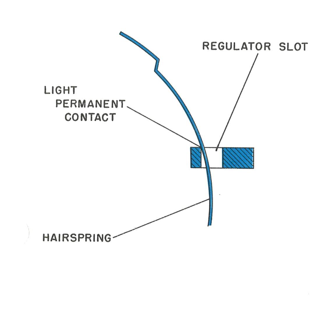
Inspect the hairspring to be certain that it is properly adjusted. The hairspring should be in light, permanent contact with the inside edge of the regulator slot, and should not leave that edge at any time during the complete maximum oscillation of the balance.
Fig. 25.7 · Hairspring & regulator slot
Date Mechanism
1 · Reassembling the Date Mechanism
Replace the date wheel assembly on the movement. The date wheel must be replaced with the large head of the bushing toward the dial.
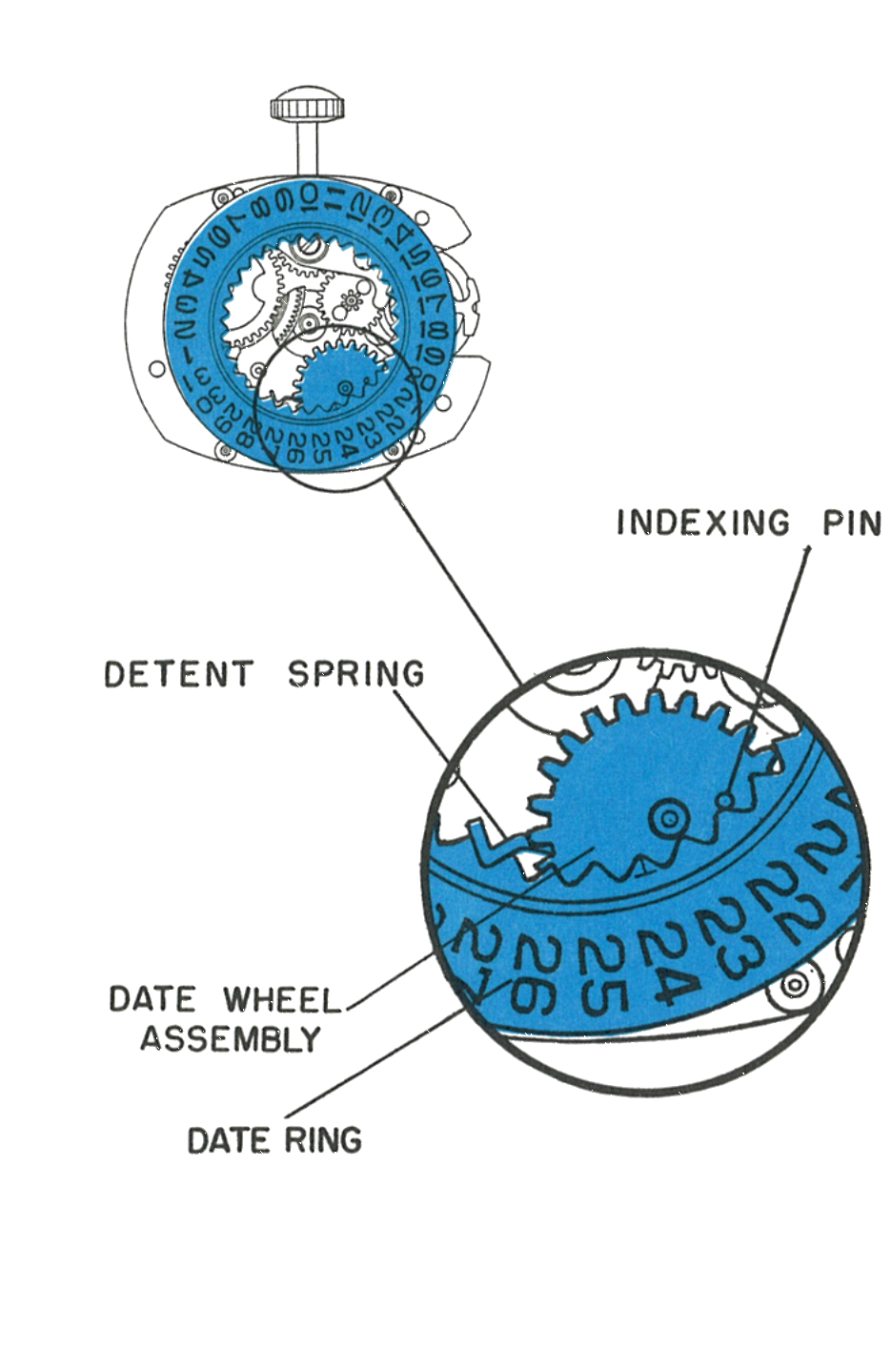
Assemble the date ring to the movement, making sure that the V shaped end of the detent spring is positioned in the space between two teeth of the date ring.
Rotate the date wheel assembly clockwise so that the indexing pin touches the exit side of the date ring tooth.
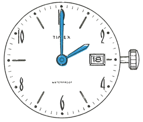
Position the dial assembly to the movement with the hands set at approximately 2 o’clock, then bend the lugs on the dial holder to clamp the dial to the movement. It is essential that the dial be clamped tight. Take care that the position of the hands, date ring and date wheel assembly are not changed during this operation.
Fig. 25.8 · Date indexing
2 · Checking the Indexing
Once the dial is clamped to the movement, the action of the date indexing can be checked. Indexing should start between the hours of 11 and 12. During the indexing, and near completion of its travel, the date ring must indicate a snapping effect, darting forward, of the date numeral to its position in the date window.
Note: If the minute hand has been removed, replace it on the dial assembly together with the friction and cannon pinions before the dial assembly is put on the movement.
Fig. 25.8 · Indexing check
3 · Replacing the Sweep Second Hand
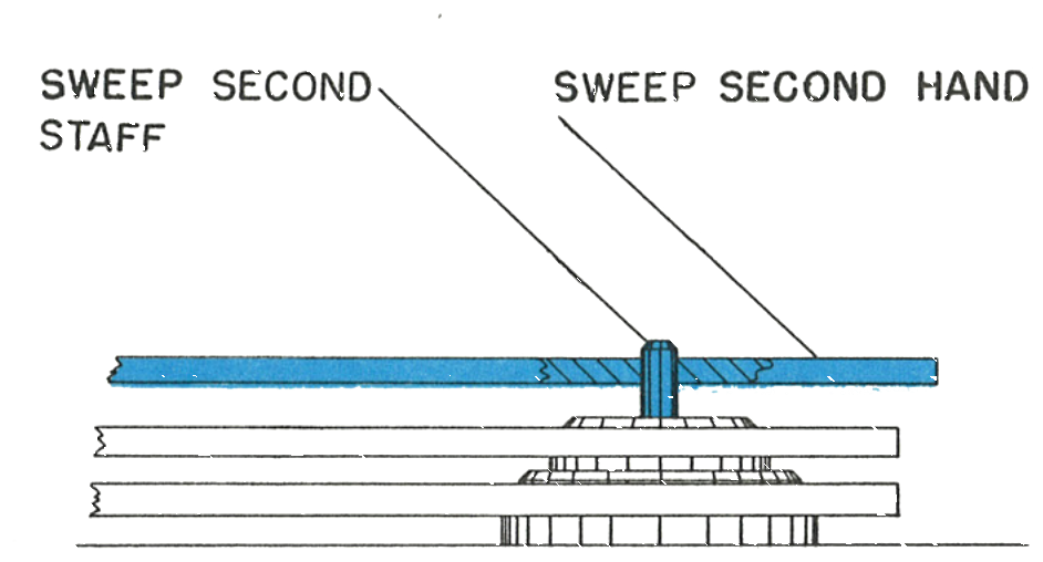
Replace the sweep second hand by driving it just below the end of the sweep second staff. Be certain the sweep hand is set below the chamfer on the top of the staff.
Fig. 25.8 · Sweep second hand
This guide is based on the original Timex factory service manual for the Model 25 movement.