
A Calendar on the Model 100
The Timex Model 101 is a 9½ ligne calendar movement with “V-Conic” balance bearings. The Model 101 movement is the same as the Model 100 movement with the addition of the calendar mechanism. The date may be advanced quickly.
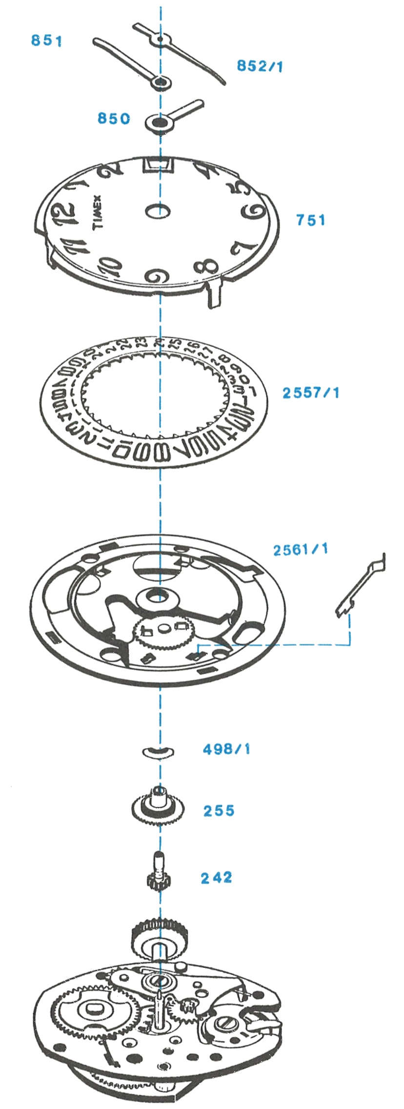
This calibre keeps the older Timex parts numbering rather than the four digit scheme used by the Model 104 and its family. The cannon pinion is 242, the dial 751, the sweep second hand 852/1, the same references used across the Model 80 family.
Exploded View
Everything below the numbered parts is the basic Model 100 movement.
Disassembly for Cleaning
Lifting Off the Calendar
Remove all hands.
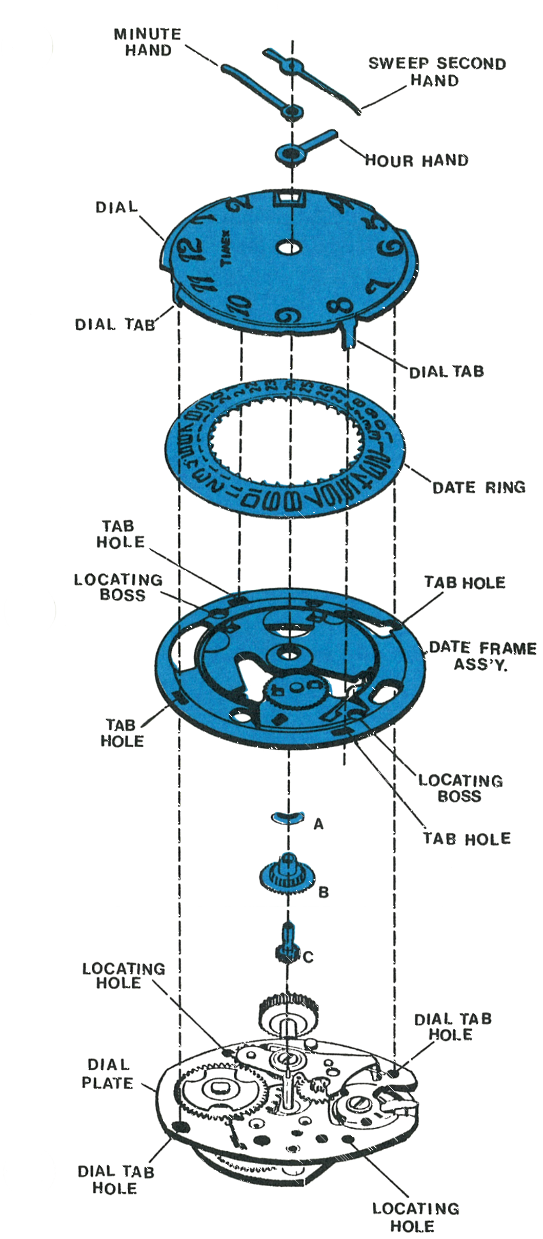
Straighten the dial tabs so they will pass through the holes and come free of the movement. Turn the assembly over and lift off the dial, the date ring and the date frame assembly.
Remove the hour wheel washer (A), the hour wheel assembly (B) and the cannon pinion assembly (C).
After the above parts have been removed, the basic movement can be disassembled, cleaned, lubricated and reassembled as outlined for the Model 100 movement.
The hour wheel washer, hour wheel assembly, cannon pinion assembly and date frame assembly may be cleaned using standard watch cleaning solutions.
Reassembly
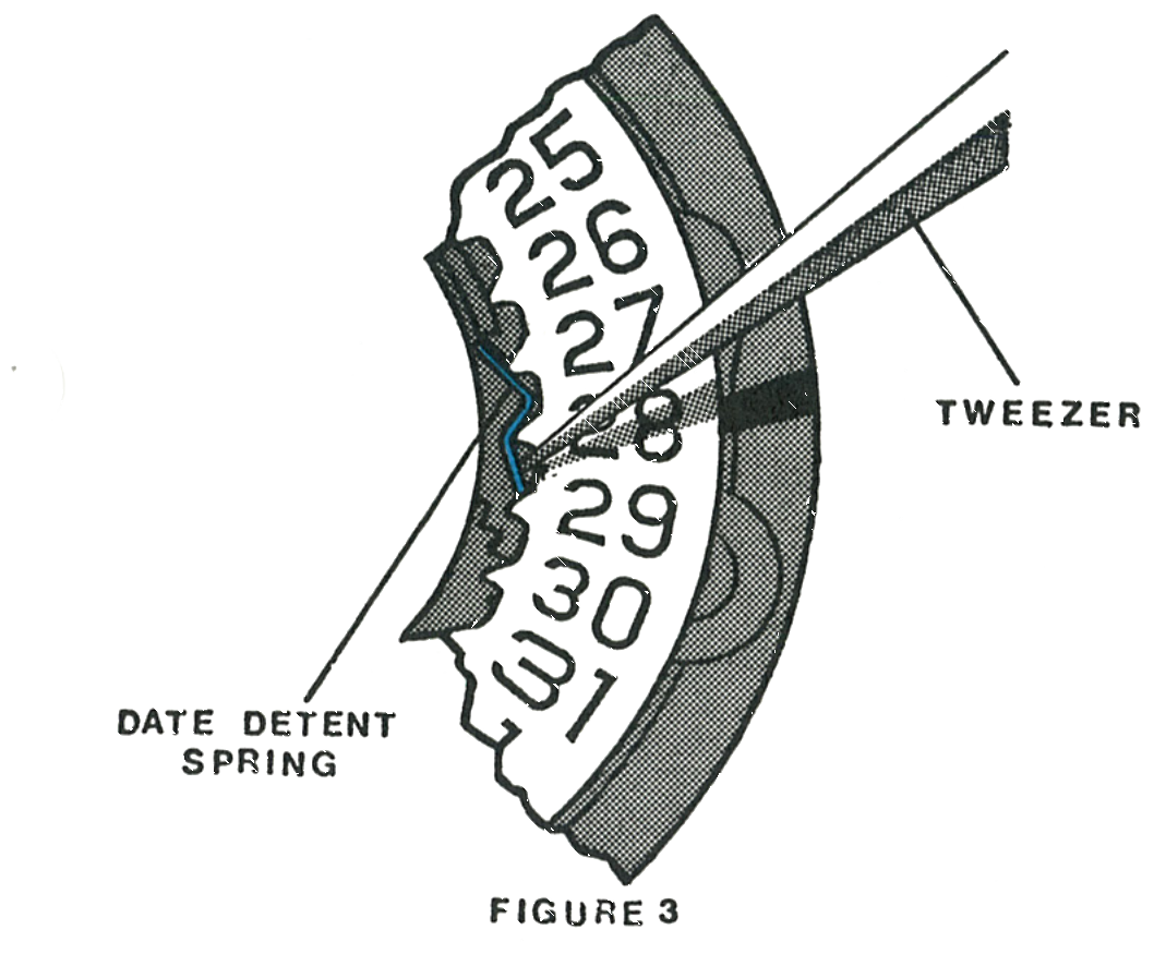
The Date Detent Spring
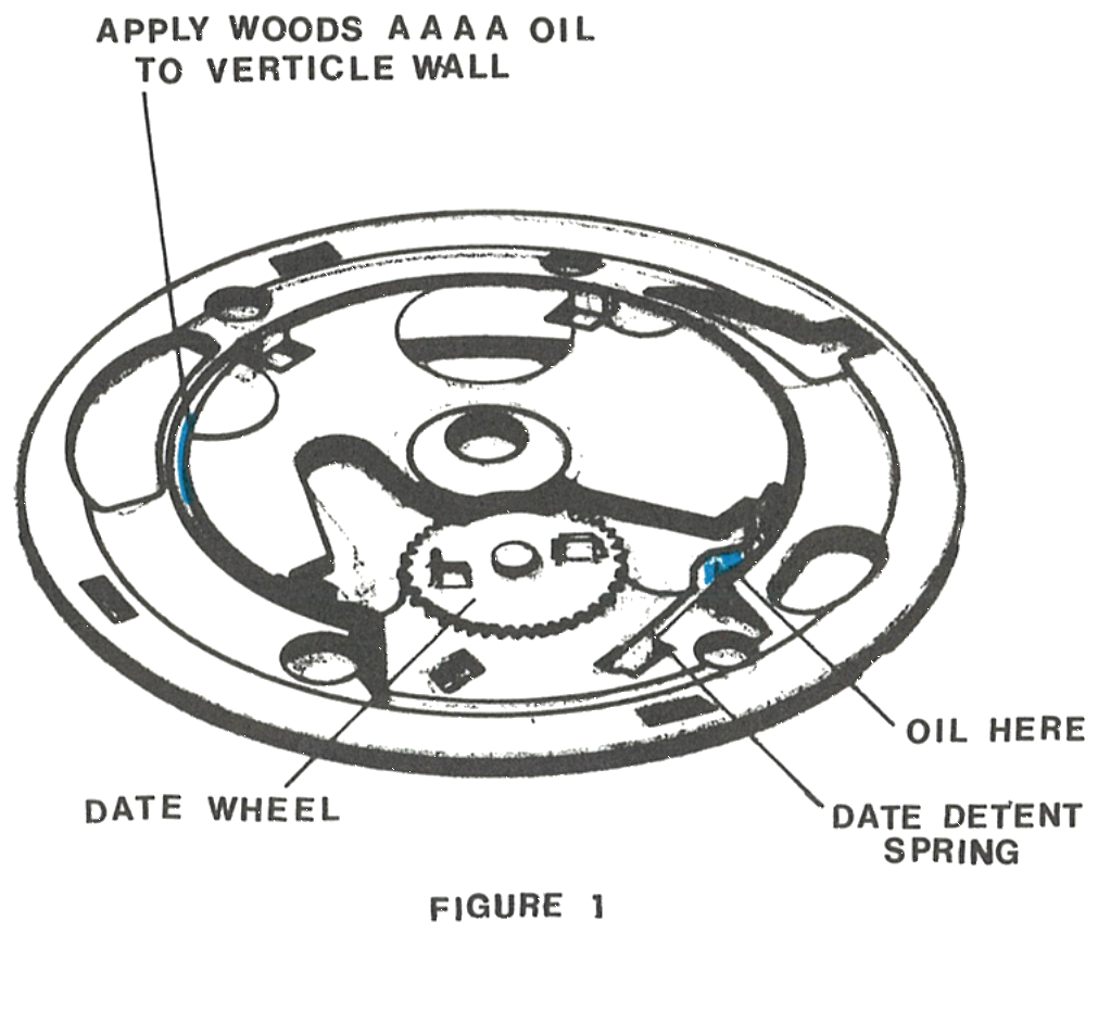
Make certain the date detent spring is correctly located in the date frame assembly.
Lubricate the bearing faces of the date detent spring with a thin film of non-spreading watch oil, Moebius Synt-A-Lube in the factory. Lubricate the vertical wall of the date frame with a thin film of spreading type watch oil, Woods AAAA in the factory.
The Cannon Pinion
Apply non-spreading watch oil to the end of the cannon pinion assembly.
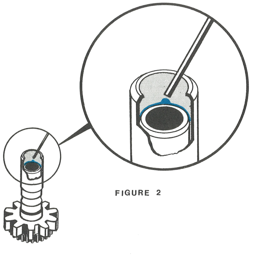
Replace the parts on the movement in this order: cannon pinion assembly, hour wheel assembly, hour wheel washer, then the date frame assembly, oriented as shown on page 101.3 with the bosses seated in the holes.
Dropping In the Date Ring
Position the date ring centrally on the date frame assembly. With a fine tweezer, deflect the date detent spring inward until the date ring drops into place.
Orient the dial as shown on page 101.3 with the window toward the crown and stem and insert the tabs through the date frame assembly into the dial plate of the movement. Hold the dial in place on the movement, turn the assembly over and bend the tabs firmly against the back of the dial plate.
Pull the crown and stem out and rotate clockwise until the date changes with a snap. Stop turning the crown immediately and assemble the hands at the 12 o’clock position.