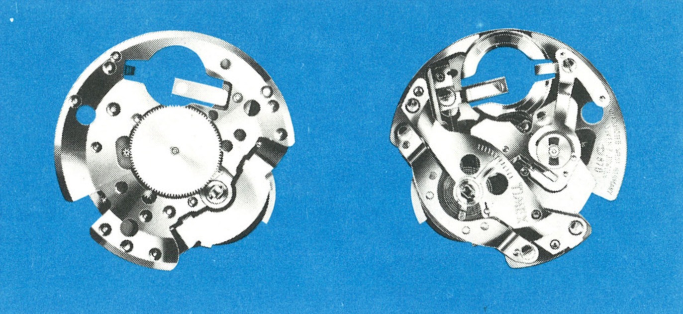
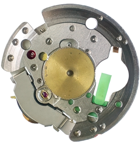
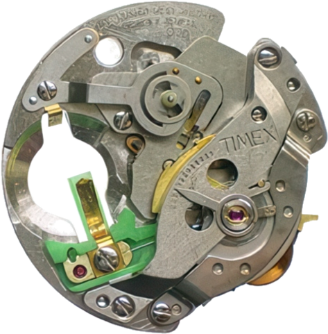
The 13½ ligne Timex Electric. The sweep second hand jumps once each second rather than beating five or six times, because the balance drives an index wheel one tooth at a time instead of an escapement.
The Timex electric has an hourly beat of 21,600. The large balance wheel has a temperature compensated hairspring and the rate can be adjusted in the usual way by moving the regulator. It can be checked in all positions on a normal watch rate recorder, and dismantled and repaired with conventional tools. For checking the battery voltage, a high ohm volt meter of about 20,000 ohms per volt is sufficient.
The Timex Model 84, caliber 870/871, is a 13½ ligne electric watch movement. The power to drive the movement is supplied by a miniature energy cell. Power from the energy cell drives the balance wheel, the balance wheel drives the time train which, in turn, rotates the hands.
Telling it from a mechanical: The sweep second hand jumps once each second rather than beating five or six times per second. That is the index wheel stepping the train one tooth at a time.
The hands are set by pulling out and turning the crown set wheel located on the back of the watch. The watch is stopped when the crown set wheel is pulled into the set position, allowing the time to be set exactly to the second, and in that position the flow of current is interrupted so the energy cell is not being discharged.
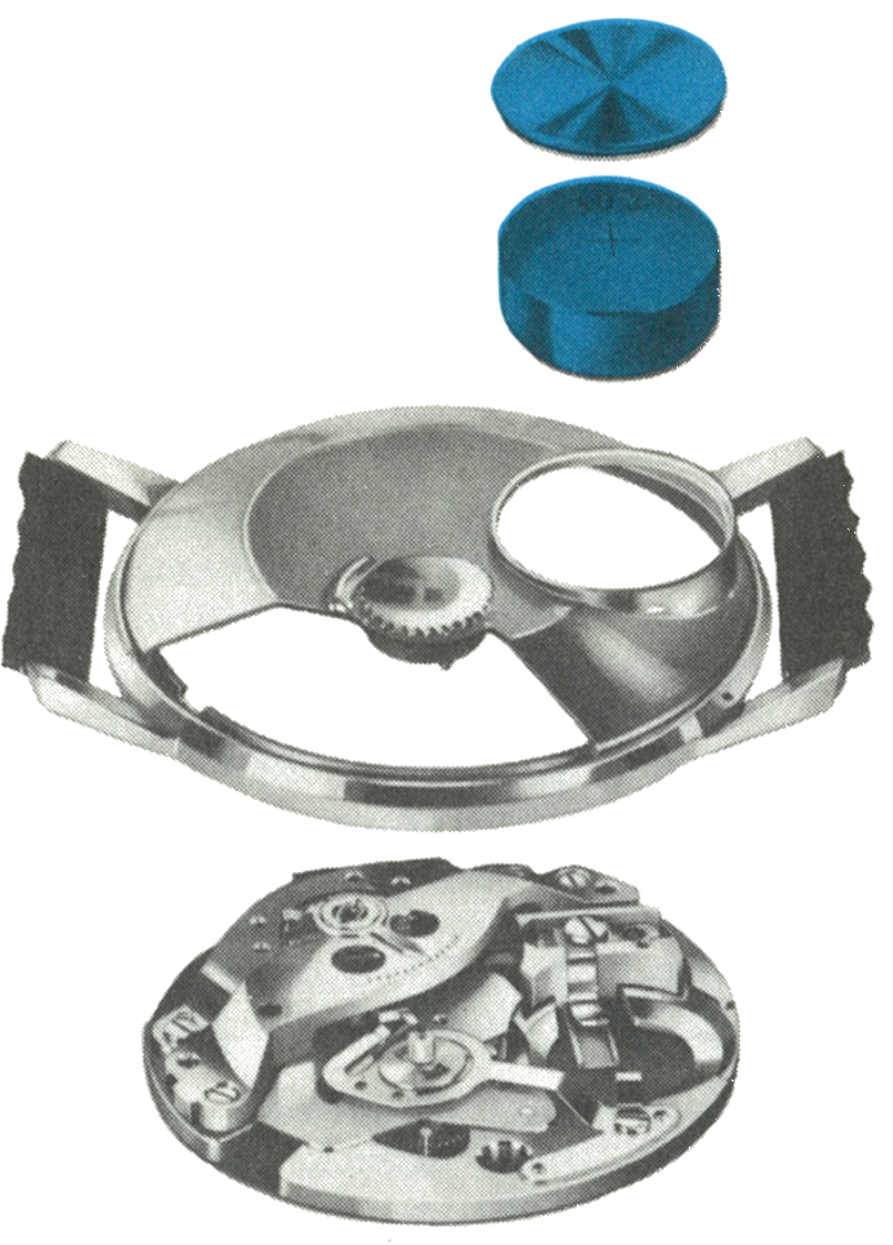
Remove the energy cell. To avoid damage to the watch case, the energy cell cover should be opened only at the spot indicated on the caseback, where an arrow and the words “lift here” are stamped. Check the voltage: any cell reading less than 1.5 volts, or one known to have been in service in excess of one year, should be replaced.
Remove the crystal using a Timex crystal lift or conventional crystal lift. The movement can now be removed through the front of the case.
Note the locating notch in the bezel seat (A) and the corresponding key on the balance bridge (B).
Caution: No attempt should be made to remove the caseback, as it is fixed in place with epoxy resin. Avoid short circuiting the cell by metallic connections between the outer case and the negative pole, as this short circuit could shorten the life of the cell.
Fig. 84.3 · Case & Energy Cell
2 · The Crown Set Wheel
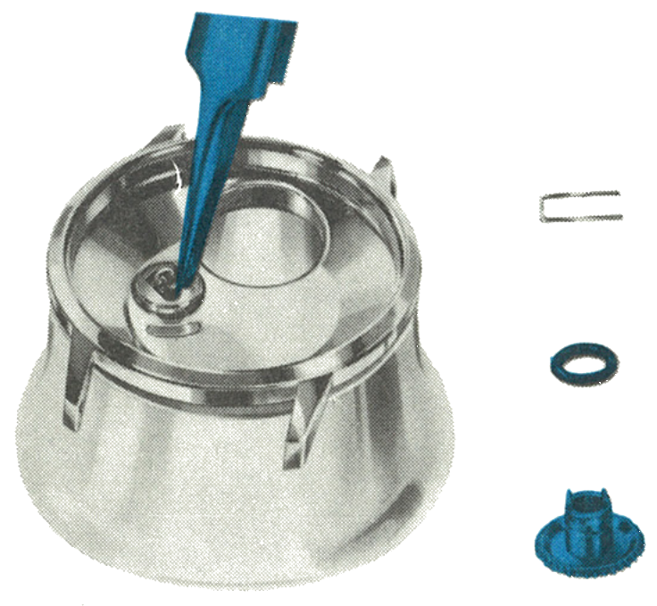
The crown set wheel remains with the caseback. An automatic coupling device connects it with the setting stem when the movement is replaced in the case.
Should it be necessary to remove it, lift the crown set wheel to the “stop” position.
Spread the retaining spring open with the tips of tweezers and push the crown set wheel down through the rear of the case. If necessary, the retaining spring and gasket can now be removed.
Fig. 84.3 · Crown Set Wheel
3 · The Energy Cell Retaining Spring
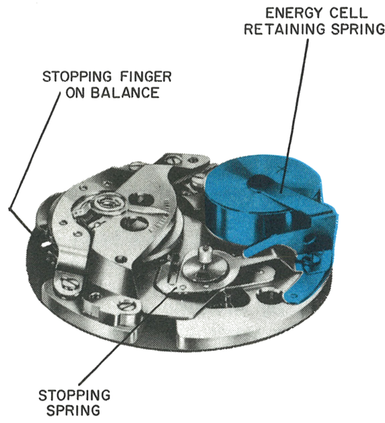
To examine the function of the movement, place it on a suitable movement ring and clamp the energy cell in place with an energy cell retaining spring, available on request from the Timex Material Sales Division. One end of this spring depresses the stopping spring fixed to the movement and allows the balance to be turned freely.
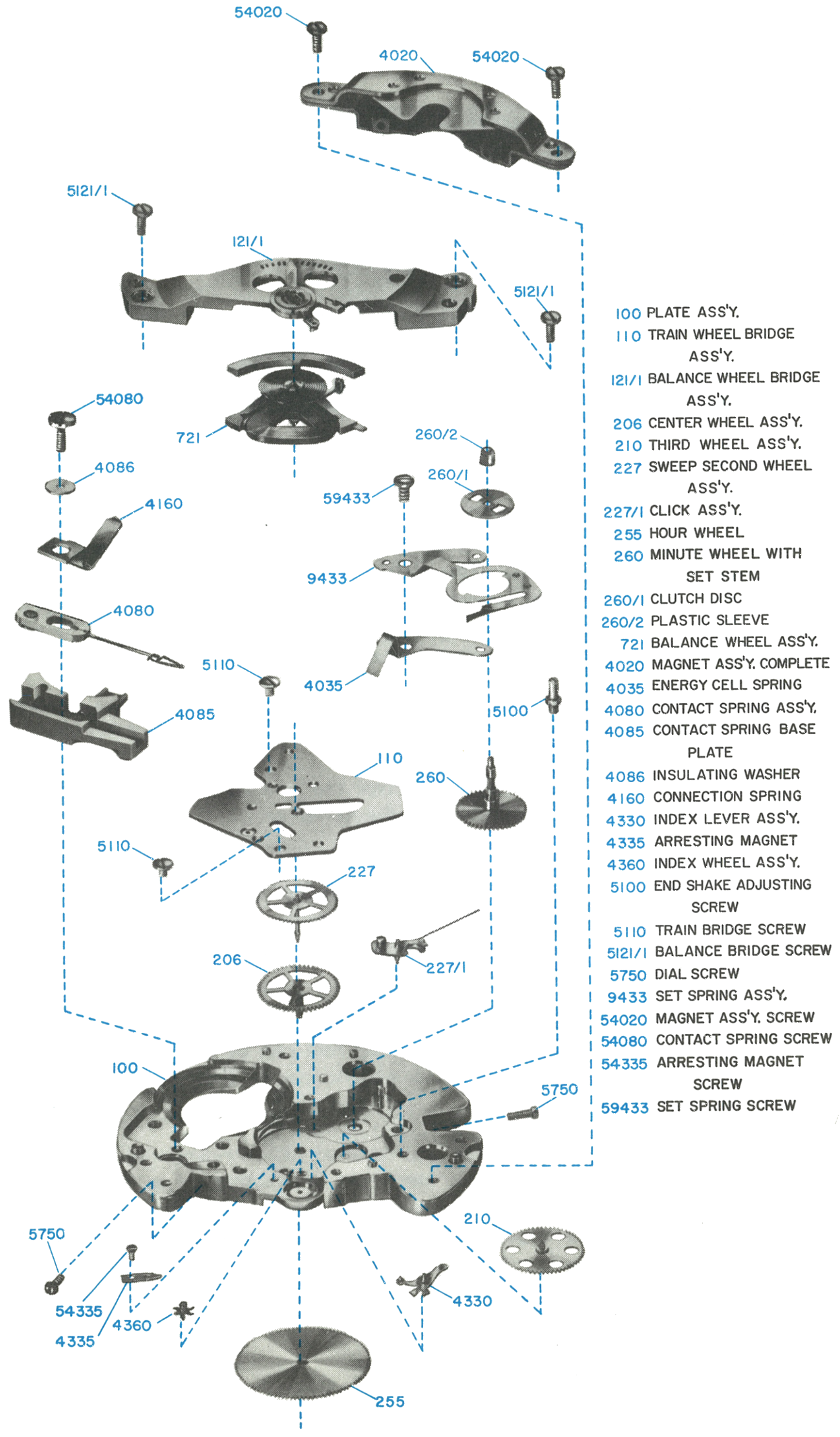
Caution: The negative pole must contact the connection spring (4160); current flows through it to the contact spring (4080), and these parts are insulated from the rest of the movement. The positive pole contacts the energy cell spring (4035) and flows to the plate (100). Never make a metallic connection between the insulated and uninsulated parts.
Fig. 84.4 · Retaining Spring
4 · Swinging the Magnet Aside
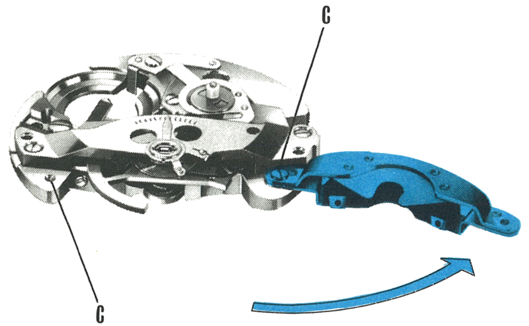
The permanent magnet system, together with the shunt bridge, can be rotated out of position so that the balance wheel and contact system are visible. To do so, remove one screw (C). If desired, this assembly may be completely removed by removing both screws (C).
Fig. 84.4 · Magnet System
The Contact System
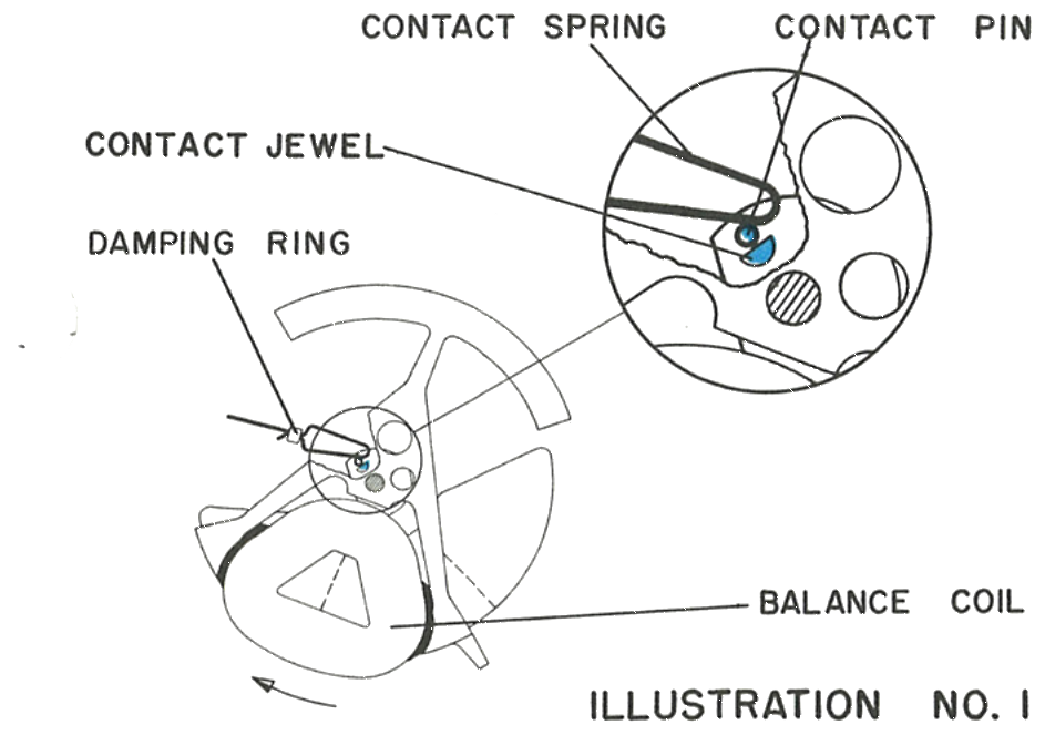
Rotate the balance wheel slowly from its rest position with a clean brush. The instant the contact spring touches the contact pin fixed on the balance wheel, current flows through the balance drive coil. The current induces a magnetic field which opposes the field of the magnet, and that opposition imparts an impulse to the balance wheel when the magnet is in place.
1 · The Contact Closing
The contact spring, contact pin, contact jewel, damping ring and balance coil.
Fig. 84.5 · Illustration 1
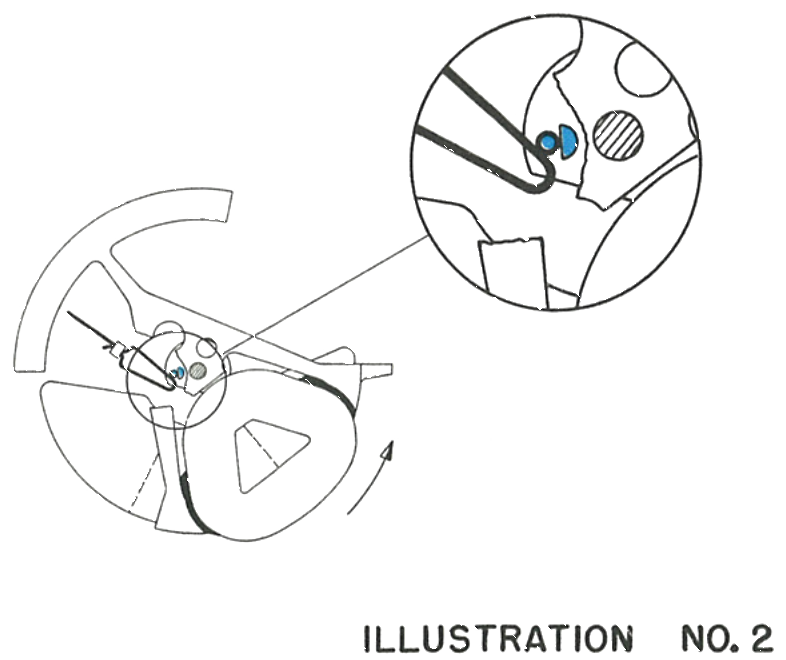
2 · The Return Stroke
After the balance wheel returns to its neutral position the same process is repeated in the opposite direction. Repeat this test several times until the drive action is fully understood.
The purpose of the contact jewel is to limit the physical contact between the contact pin and contact spring, so that the flow of electrical energy occurs at a precise position during the rotation of the balance wheel. The function of the remainder of the movement is fully mechanical. Before any further work is carried out, the energy cell should be removed to prevent the possibility of a short circuit.
Fig. 84.5 · Illustration 2
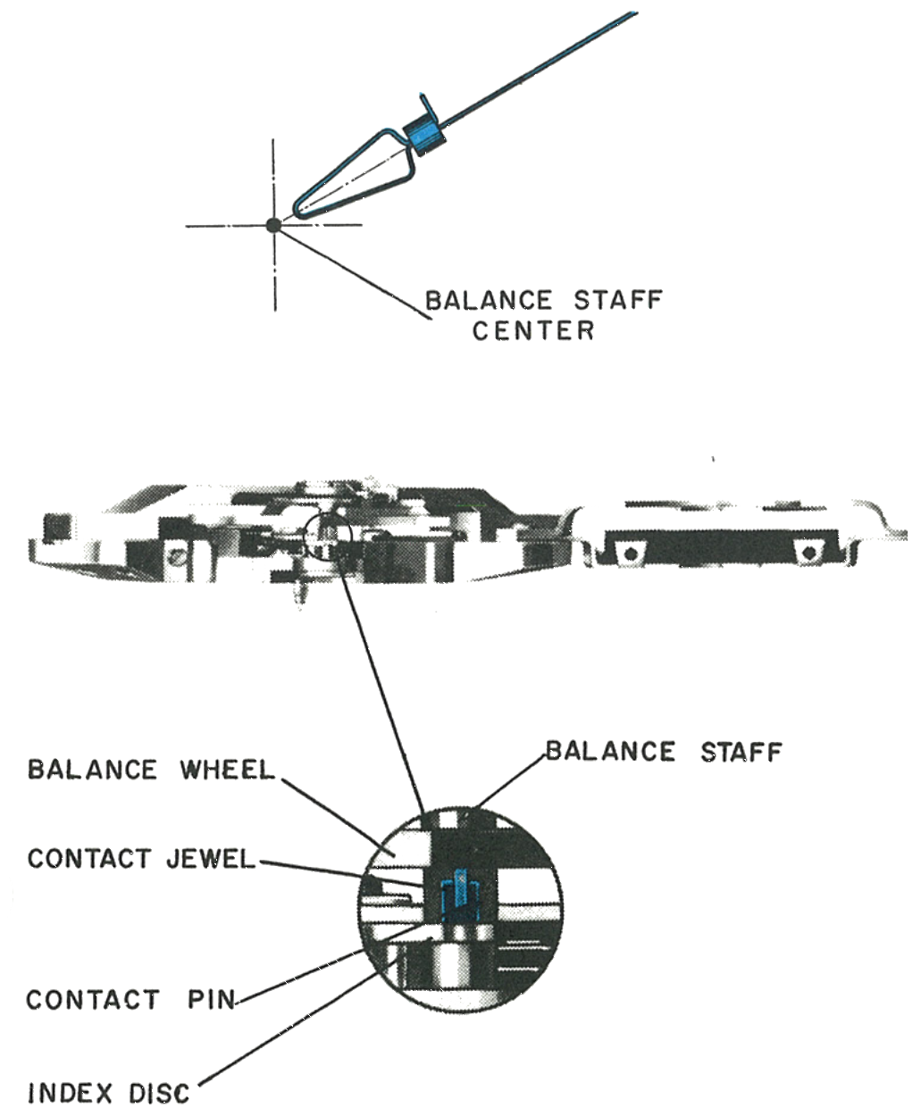
3 · Where the Contact Spring Must Sit
The contact spring must be pointing exactly to the centre of the balance staff, and centred horizontally between the index disc and the balance wheel.
Caution: The contact spring requires very careful treatment. Protect it from scratches and deforming, avoid excessive bending, and do not touch the contact area at the end of the spring. Handle it with the same care as a hairspring. Its length is fixed at the factory and no attempt should be made to adjust it.
Fig. 84.5 · Contact Spring
Never oil the contact: The contact pin, contact jewel and contact spring must not be oiled. Oil on these parts would interrupt the flow of current to the drive coil.
Setting & Stopping
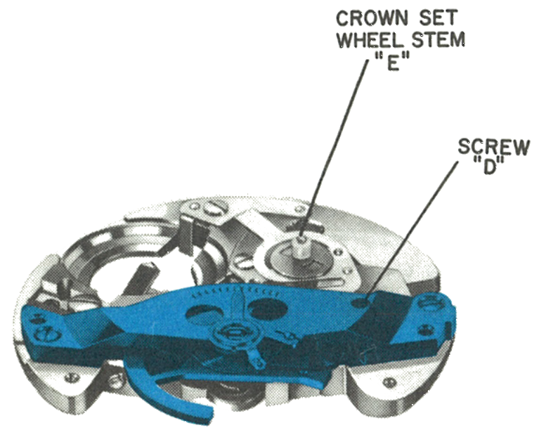
1 · The Balance Bridge
After removal of the permanent magnet, the balance bridge and balance wheel can be removed. Screw (D) serves to adjust endshake of the balance and is fixed in place with epoxy. The hairspring stud may be pressed out of the balance bridge to separate bridge and balance wheel.
The crown set wheel stem (E) is also the staff of the minute wheel and, as such, is connected to the crown set wheel on the caseback through a clutch device.
Fig. 84.6 · Balance Bridge
2 · Running Position
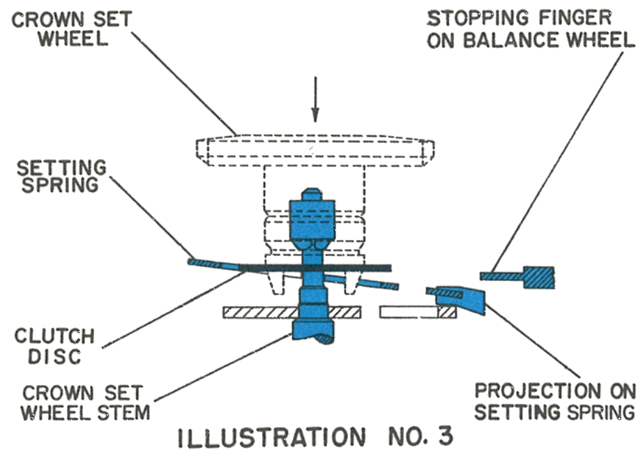
The crown set wheel is depressed to its running position. The clutch disc is kept out of engagement with the stem and the setting spring is depressed, so the projection on the setting spring is kept out of engagement with the stopping finger of the balance wheel.
Fig. 84.6 · Illustration 3
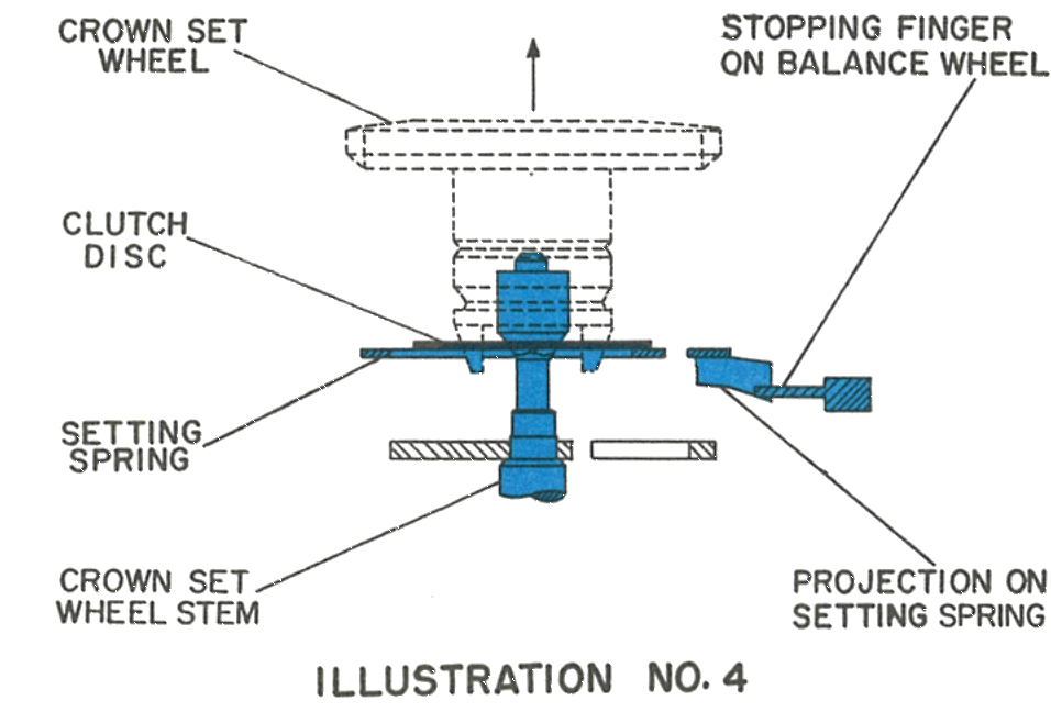
3 · Set Position
The clutch disc now engages with the square portion of the stem and couples the stem and crown set wheel, allowing the hands to be set. This position also allows the setting spring to move upwards and butt against the stopping finger on the balance wheel, stopping it.
Fig. 84.6 · Illustration 4
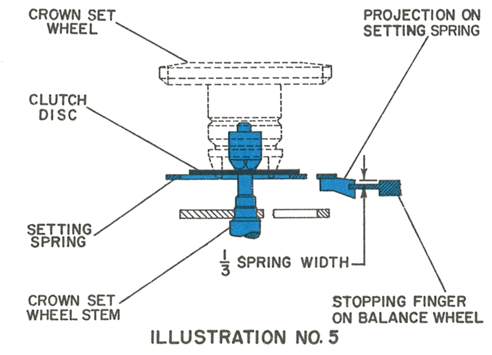
4 · Adjusting the Setting Spring
Move the crown set wheel upwards so the clutch disc is just out of engagement with the square portion of the set stem, resting against the bottom of the square. In this position the projection on the setting spring must contact the stopping finger on the balance wheel by the amount shown, one third of the spring width.
When the crown set wheel is then pulled into the set position, the stopping finger on the balance wheel must be in full contact with the projection on the setting spring.
Fig. 84.6 · Illustration 5
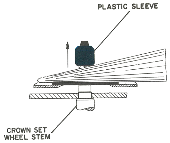
5 · Removing the Clutch
Lift the plastic sleeve from the stem with tweezers as shown, then remove the clutch disc. Finally remove the screw holding the setting spring to the plate and remove the setting spring. The crown set stem will remain with the movement.
Fig. 84.7 · Plastic Sleeve
6 · The Contact Spring and Connection Spring
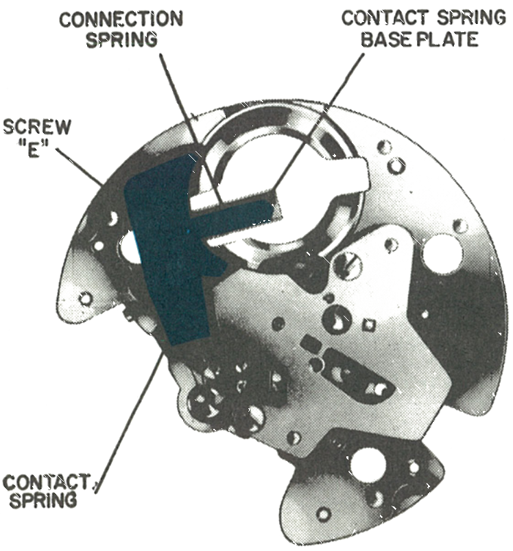
Now remove the contact spring, contact spring base plate and connection spring.
Caution: Note the insulating washer beneath screw (E). Be certain to replace it, otherwise a short circuit will occur.
Fig. 84.7 · Springs
The Index Train
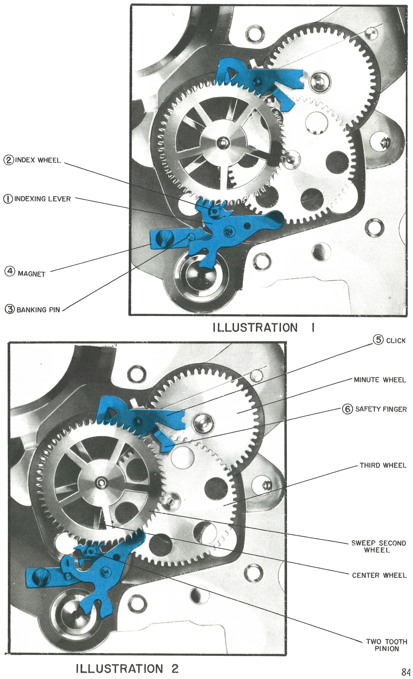
When the balance wheel moves clockwise it moves the index lever to the right. The pin moves the index wheel backwards slightly until it clears the tooth, and the moment it does, magnetic attraction retracts the wheel back to its original position, set for another one-tooth advancement on the next counterclockwise rotation.
When the balance wheel moves counterclockwise it moves the indexing lever to the left. The lever contains a steel “D” shaped pin which advances the index wheel forward one tooth, after which the lever comes to rest against the banking pin. The tip of one tooth on the index wheel is attracted and held in position by the magnet, so the pin cannot move out of its position between the teeth of its own accord.
1 · The Two Positions
When the index wheel has been moved forward three teeth, one tooth of the two-toothed pinion fixed to it engages the sweep second wheel and rotates it forward one tooth. That one tooth rotation, aided by the click, provides the one second jump of the sweep second hand. The safety finger ensures that no more than one tooth of the sweep second wheel will index at a time.
Fig. 84.9 · Illustrations 1 and 2
2 · The Third Wheel Friction
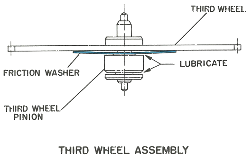
The dial train friction is provided by the third wheel assembly. A friction washer is interposed between the third wheel pinion and the third wheel. It is important to carefully lubricate this as indicated after cleaning.
Fig. 84.10 · Third Wheel
3 · The Arresting Magnet
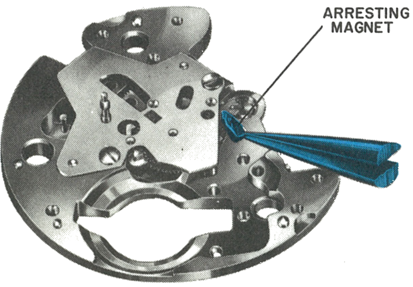
The index magnet may be removed to check the train. During removal of the magnet, the index lever must be in the position shown in illustration 1.
Note: When assembling the hands, support the sweep second wheel assembly at the pivot to avoid damage. When recasing, pull the crown set wheel out into set position.
Fig. 84.10 · Arresting Magnet
Cleaning & Lubrication
1. The movement may be cleaned in the usual method using normal watch cleaning and rinsing solutions. The balance and contacts must be cleaned separately to prevent damage to the coil and contact spring. Do not clean the energy cell with any liquid; if necessary it should be wiped with a dry cloth only.
2. After cleaning, any particles adhering to the magnet should be carefully removed before assembly. A piece of scotch tape rolled to a point will be found useful. This process should not be used when the movement is assembled, as there is danger of severing the lead wires of the balance coil.
3. The movement should be re-oiled in the normal manner using only high grade watch oils. Hamilton PML 79 is used in factory assembly. Under no circumstances should oil or grease containing silicone be used.
The points requiring lubrication are the jewel bearings and pivots of the train wheels and balance; the minute wheel and set stem bearing surfaces; the steel “D” shaped pin on the index lever; the surface of the click which rests against the sweep second wheel; the third wheel assembly; and the pipe of the crown set wheel, so the lubricant will seep down to the rubber waterproofing gasket which surrounds it.
The impulse pin: Lubricate the impulse pin on the balance wheel lightly if it is steel. In later models it was replaced by a jewel impulse pin, which should not be lubricated.
4. The best performance is achieved if the hairspring does not vibrate between the pin and key of the regulator. The outside edge of the hairspring should be in light permanent contact with the inside edge of the regulator key.
Caution: Never lubricate the contact pin on the balance or any part of the contact spring assembly. Since the watch contains permanent magnets, no attempt should be made to demagnetize it.
This guide is based on the original Timex factory service manual for the Model 84 movement.