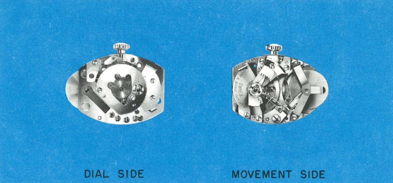
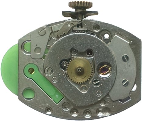
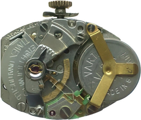
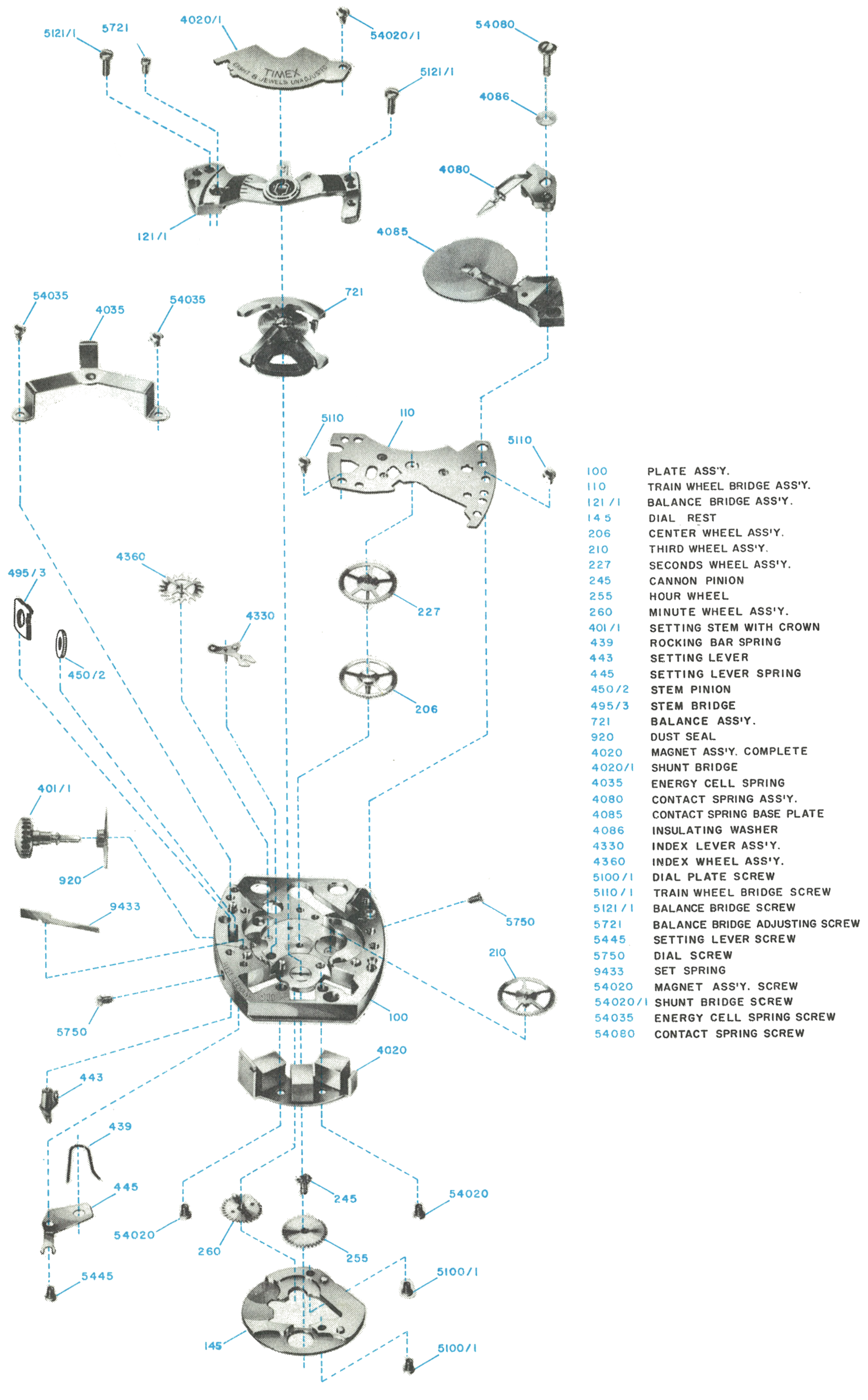
The manual opens by calling it the world’s first ladies’ electric wrist watch. An energy cell drives the balance directly, the balance drives the train, and it comes apart with ordinary watchmaking tools.
The hands are set by the normal method, pulling out and rotating the crown. The Model 82 incorporates a drive which stops the movement when the crown is in the set position. In this position the flow of current from the energy cell is interrupted and the cell is not being discharged.
The Timex Model 82 is the world’s first ladies’ electric wrist watch. The power to drive the movement is supplied by a miniature energy cell. Power from the energy cell drives the balance wheel, the balance wheel drives the time train which, in turn, rotates the hands.
The Model 82 has an hourly beat of 21,600. The large balance has a temperature compensated hairspring and the rate can be adjusted in the usual way by moving the regulator. It can be checked in all positions on a normal watch rate recorder.
Tools: It can be dismantled and serviced with conventional tools. No special knowledge of electricity or electronics is needed, and a high ohm volt meter of about 20,000 ohms per volt is sufficient for checking the cell.
Cells: The energy cell is guaranteed for 12 months. Use only genuine Timex Energy Cells, Type B. Other types may not deliver the necessary voltage or life and may leak, seriously damaging the movement.
The balance coil sits at the 6:00 end, and it is what you work around the whole time.
1 · Out of the Case
Pull the crown into the set position.
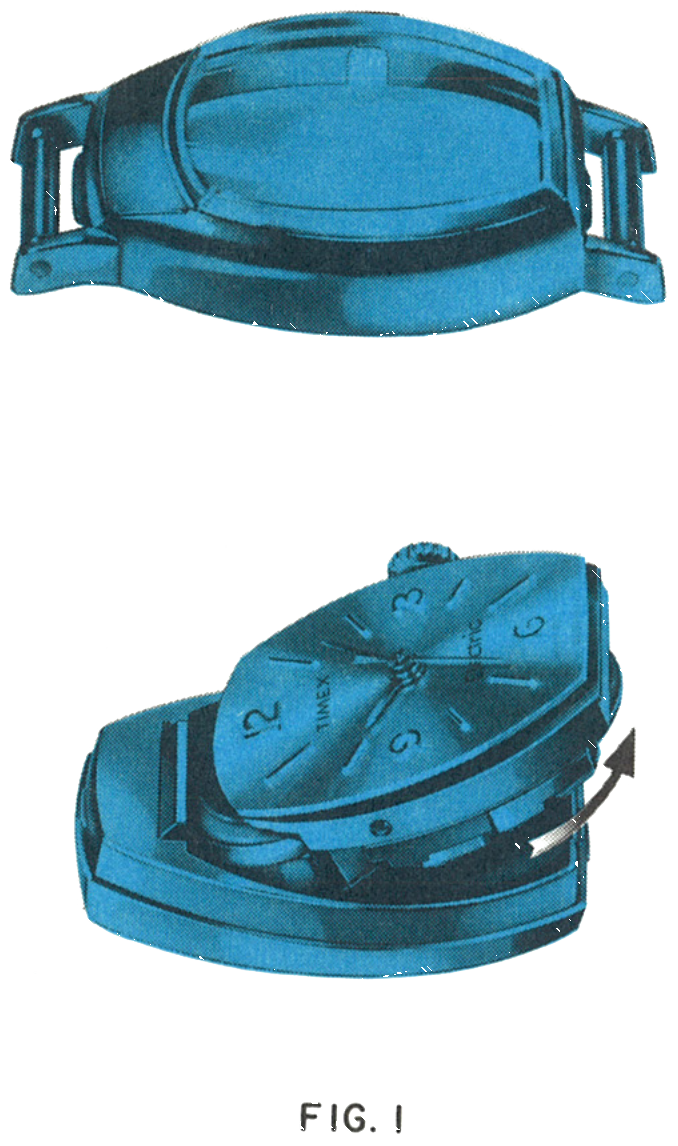
Separate the bezel and caseback. The movement will remain with the caseback, held captive at the 12:00 end by a projection of the caseback.
To remove the movement from the caseback, lift the movement at the 6:00 end, exercising caution to avoid striking or damaging the balance coil which is located at this end. When the 6:00 end is completely free, slide the movement out, again taking care not to damage the coil.
Fig. 82.3 · Figure 1
2 · The Energy Cell
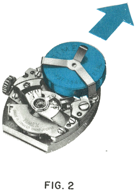
Remove the energy cell by sliding it out in the direction of the arrow. Check the voltage: any cell reading less than 1.30 V, or one which has been in service in excess of one year, should be replaced.
Caution: Avoid short circuiting the cell between the outer case and the negative pole. Do not dispose of an energy cell in fire.
Fig. 82.3 · Figure 2
3 · Onto a Movement Ring
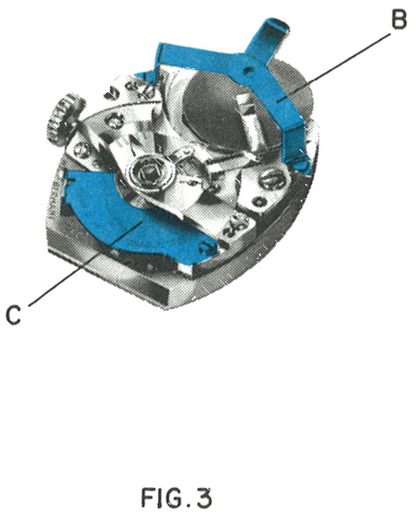
To examine the function of the movement, place it in a suitable movement ring. Special movement rings made expressly for the Model 82 may be obtained free of charge from the Timex Material Sales Division.
Remove the dial plate (A) and the energy cell spring (B), then the shunt bridge (C).
Fig. 82.4 · Figure 3
4 · The Permanent Magnet
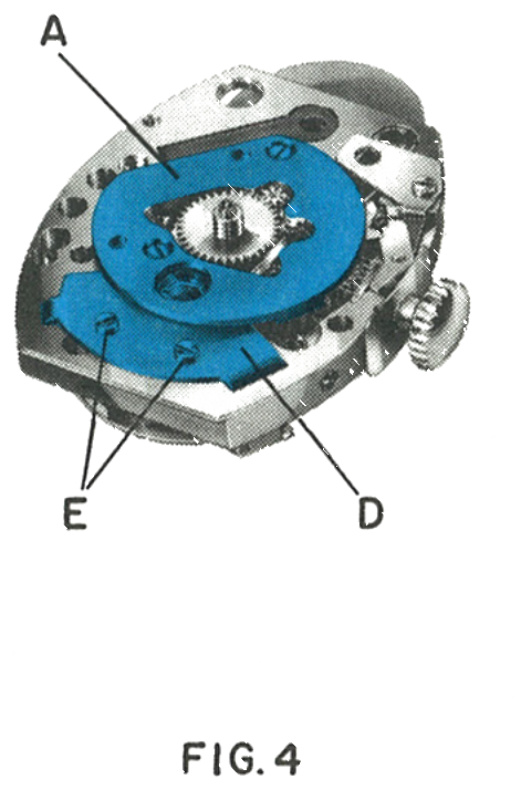
Remove the permanent magnet system (D) by removing screws (E).
Fig. 82.4 · Figure 4
The Contact System
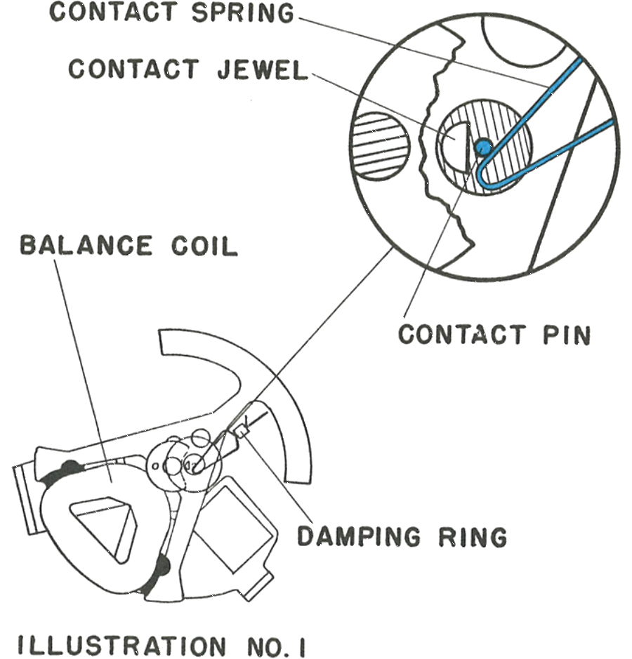
Rotate the balance wheel slowly from its rest position with a clean brush. The instant the contact spring touches the contact pin fixed on the balance, current flows through the balance drive coil. The current induces a magnetic field around the coil which interacts with the field of the permanent magnet, and that interaction imparts an impulse to the balance when the magnet is in place.
1 · The Contact Closing
The contact spring, contact jewel, contact pin, balance coil and damping ring, with the contact shown enlarged.
Fig. 82.5 · Illustration 1
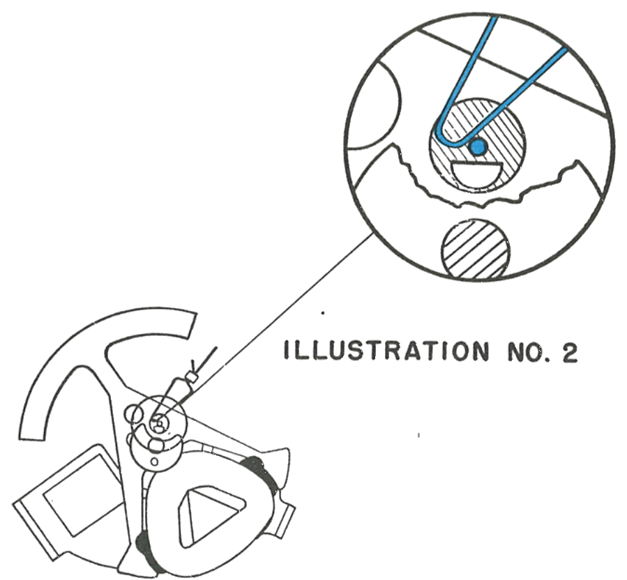
2 · The Return Stroke
After the balance returns to its neutral position, the same process is repeated in the opposite direction. Repeat this test several times until the drive action is fully understood.
The purpose of the contact jewel is to limit the physical contact between the contact pin and contact spring, so that the flow of electrical energy occurs at a precise position during the rotation of the balance.
Fig. 82.5 · Illustration 2
3 · Where the Contact Spring Must Sit
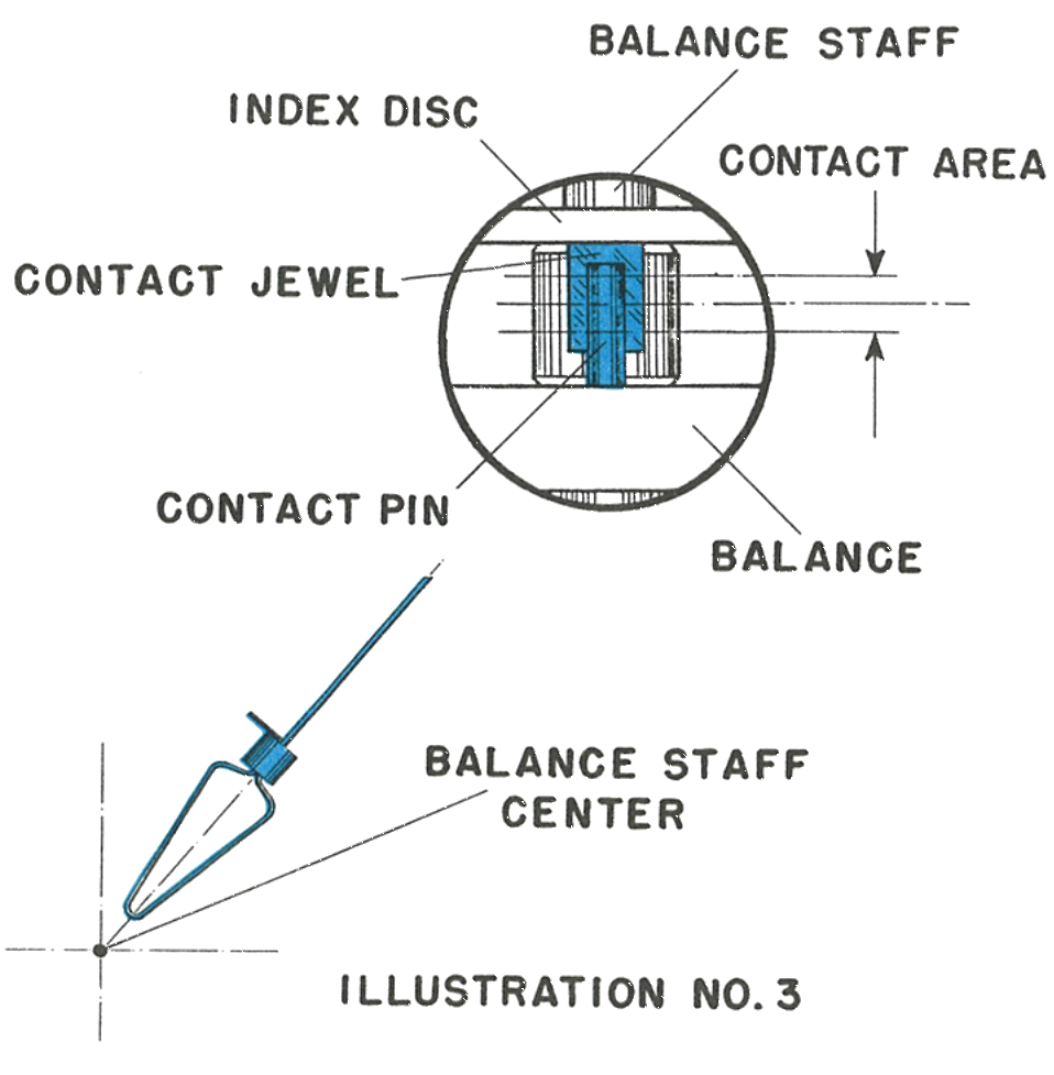
The contact spring must be pointing exactly to the centre of the balance staff, and centred horizontally between the index disc and the balance.
Caution: The contact spring requires very careful treatment. Protect it from scratches and deforming, avoid excessive bending, and do not touch the contact area at the end of the spring. Handle it with the same care as a hairspring.
Fig. 82.5 · Illustration 3
Never oil the contact: The contact pin, contact jewel and contact spring must not be oiled. Oil on these parts would interrupt the flow of current to the drive coil.
4 · Removing the Contact Spring
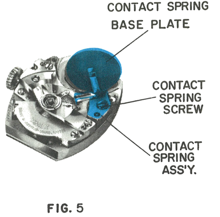
Remove the contact spring screw and the insulating washer beneath it. The contact spring assembly and contact spring base plate can now be removed.
Next remove the balance bridge and balance. The hairspring stud may be pressed out of the balance bridge to separate balance and bridge.
5 · The Entry Position
The index lever with its indexing pins and arresting magnets, shown entering.
Note: It is important to replace this insulating washer when reassembling, otherwise a short circuit in the energy cell can occur.
Fig. 82.6 · Figure 5
The Index Mechanism
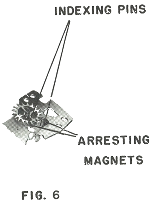
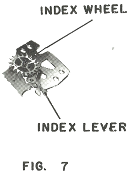
The index jewel on the balance moves the lever. The indexing pins on the lever move the index wheel to a position whereby the arresting magnet on the lever will attract and hold a tooth on the index wheel. Every half cycle of the balance will move the index wheel forward one tooth.
1 · A · Entry
The index lever with its indexing pins and arresting magnets, entering.
Fig. 82.6 · Figure 6
2 · B · Exit
The same lever and index wheel at the exit position.
Fig. 82.6 · Figure 7
Train & Stopping
Past the index wheel the Model 82 is a conventional gear train.
1 · The Gear Train
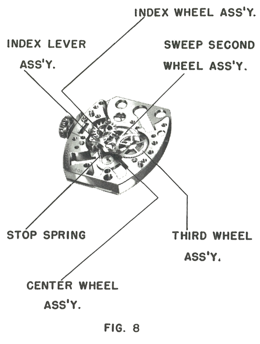
With the train bridge removed, the index wheel pinion drives the sweep second wheel, the sweep second pinion drives the third wheel, and the third wheel pinion in turn drives the center wheel.
2 · The Stopping Mechanism
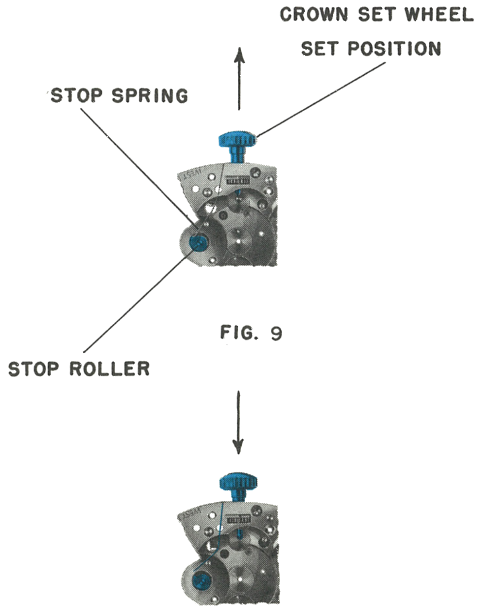
When the crown is pulled out to its set position, the stop spring engages with the stop roller on the balance. When the crown is in its normal position the stop spring is free of the roller and the balance is free to oscillate.
Fig. 82.7 · Figure 8
3 · B · Stopping
Pulled out to set, the stop spring engages the stop roller on the balance. In the normal position the spring is free of the roller and the balance oscillates.
Fig. 82.7 · Figures 9 and 10
Cleaning & Lubrication
Lubricant change, June 1974: Timex Service Bulletin No. 111 replaced the factory oil for this model. Moebius Synt-A-Lube oil is used instead of Elgin M56B oil. (It supersedes Bulletin No. 108.)
1. The movement may be cleaned in the usual method using normal watch cleaning and rinsing solutions. The balance and contacts must be cleaned separately to prevent damage to the coil and contact spring. Do not clean the energy cell with any liquid; if necessary it should be wiped with a dry cloth only.
2. After cleaning, any particles adhering to the magnet should be carefully removed before assembly. A piece of scotch tape rolled to a point will be found useful. This process should not be used when the movement is assembled, as there is danger of severing the lead wires of the balance coil. The other parts of the movement must be free of particles, especially anything that would be attracted by the magnet.
3. The movement should be re-oiled in the normal manner using only high grade watch oils. Hamilton PML 79 is used in factory assembly. Under no circumstances should oil or grease containing silicone be used.
The particular points requiring lubrication are the jewel bearings and pivots of the train wheels and balance; the stem bearing surface; the set lever and set pinion; the contact face on two teeth of the index wheel; the minute pinion bearing surface; and the bearing surface between the stem pinion and stem pinion washer.
4. The best performance is achieved if the hairspring does not vibrate between the pin and key of the regulator. The outside edge of the hairspring should be in light permanent contact with the inside edge of the regulator key.
Caution: Never lubricate the contact pin on the balance or any part of the contact spring assembly. Since the watch contains permanent magnets, no attempt should be made to demagnetize it.
This guide is based on the original Timex factory service manual for the Model 82 movement.