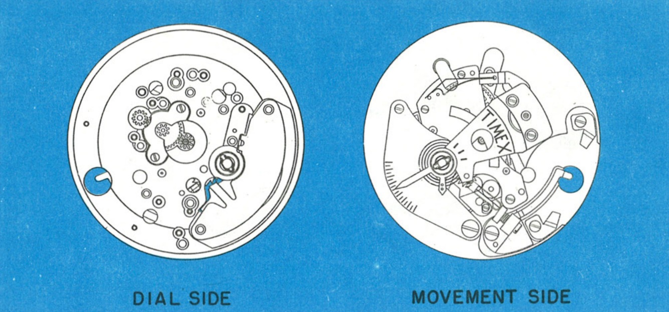
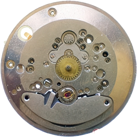
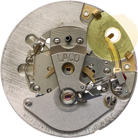
A 13½ ligne electric with a jumping second, and a caseback fixed shut with epoxy resin. The movement comes out from the dial side, and the 861 carries an overbanking lever the 860 does not.
The Timex electric has an hourly beat of 21,600. The large balance has a temperature compensated hairspring and the rate can be adjusted in the usual way by moving the regulator. It can be checked in all positions on a normal watch rate recorder, and dismantled and repaired with conventional tools. For checking the energy cell voltage, a high ohm volt meter of about 20,000 ohms per volt is sufficient.
The Timex Model 67, caliber 861 and 860, is a 13½ ligne electric watch movement. The power to drive the movement is supplied by a miniature energy cell. Power from the energy cell drives the balance, and the balance drives the time train which rotates the hands. The sweep second hand jumps once each second rather than beating five or six times per second as in a conventional watch.
861 against 860: The caliber 861 incorporates an overbanking lever not used in the caliber 860. The 860 also lacks the flat energy cell insulator and the two side energy cell springs, using a shaped plastic insulator instead.
The hands are set by pulling out and turning the crown set wheel located on the back of the watch. The watch is stopped when the crown set wheel is pulled into the set position, allowing the time to be set exactly to the second, and in that position the flow of current is interrupted so the cell is not being discharged.
Cells: Use only genuine Timex Energy Cells, Type A. Other types may not deliver the necessary voltage or life and may leak, seriously damaging the movement.
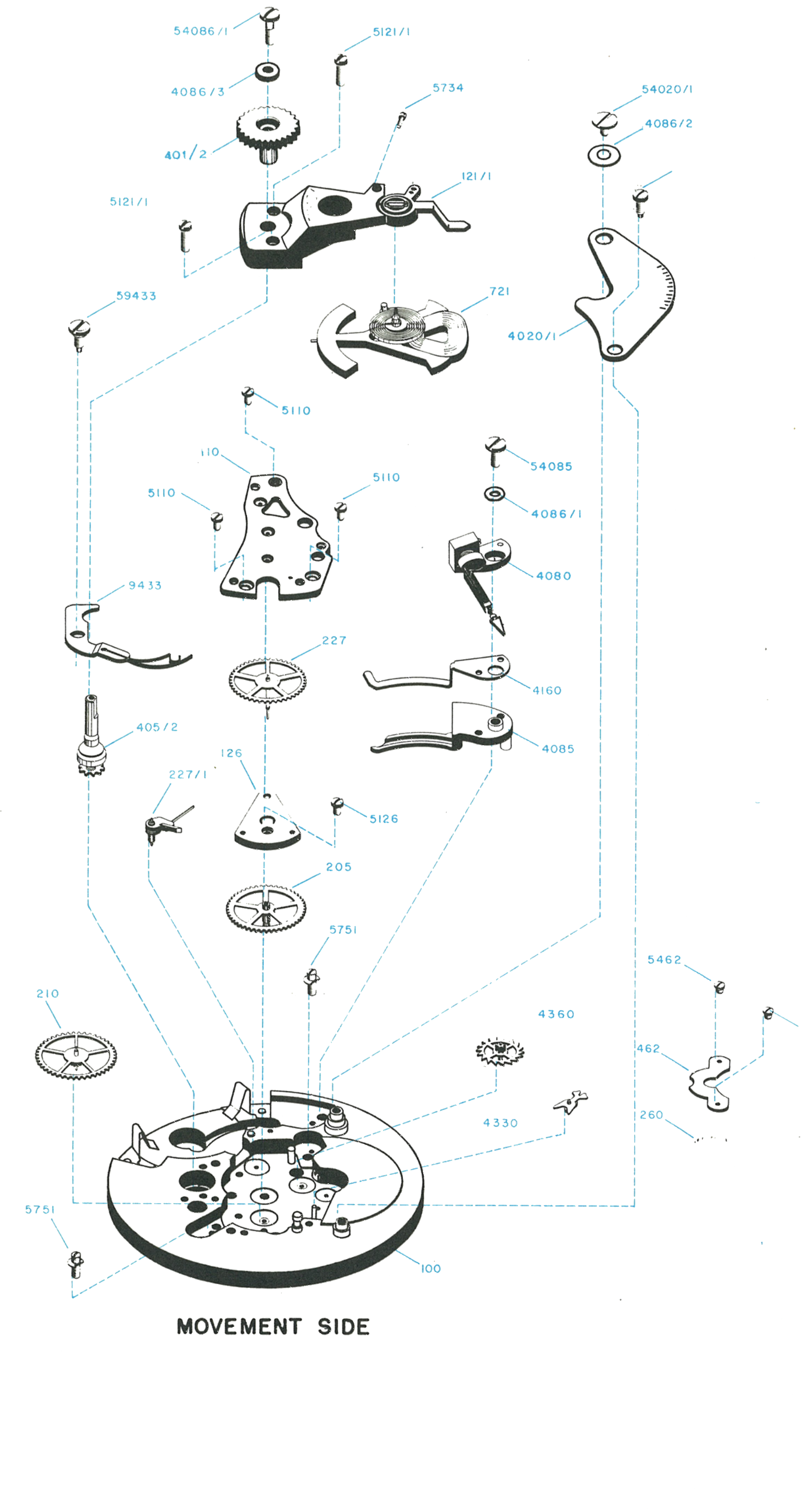
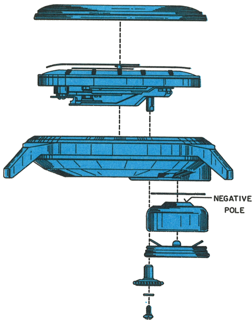
Shown from the movement side and the dial side. Three of the parts numbered 4086 are insulating: a ring, a plastic washer for the shunt bridge, and a waterproofing washer.
Before lifting the movement out of the case, first remove the energy cell from the watch case. To avoid damage to the case, the energy cell cover should be opened with a case opener only at the spot indicated for this purpose.
After unscrewing the set wheel screw, remove the setting wheel.
Using a Timex crystal lift or a conventional crystal lift, remove the crystal from the case. The movement can now be removed from the case, taken out from the dial side.
Caution: No attempt should ever be made to remove the caseback, as it is fixed in place with epoxy resin.
Fig. 67.3 · Figure 1
Cases without a cell cover: A small percentage of cases have no energy cell cover on the back. Remove the setting wheel first, then the crystal, take the movement out, and finally remove the energy cell and its parts from the recess in the caseback.
2 · The Upper Shunt
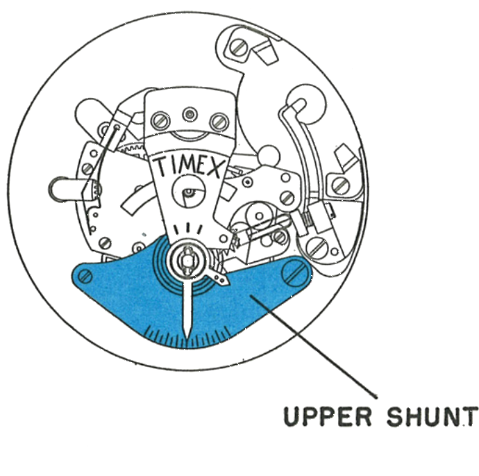
To understand the function of the electrically impulsed balance wheel, place the movement dial down on a suitable movement holder and take off the upper shunt. This applies to the caliber 861 movement.
Fig. 67.3 · Figure 2
3 · The Driving Parts
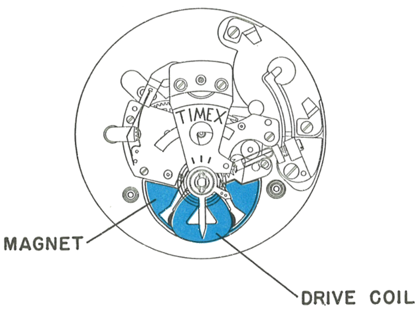
The construction of the driving parts can now readily be seen. The large, specially shaped balance with its drive coil, and a large shaped magnet, are evident upon removal of the upper shunt.
Fig. 67.4 · Figure 3
4 · The Insulating Cap
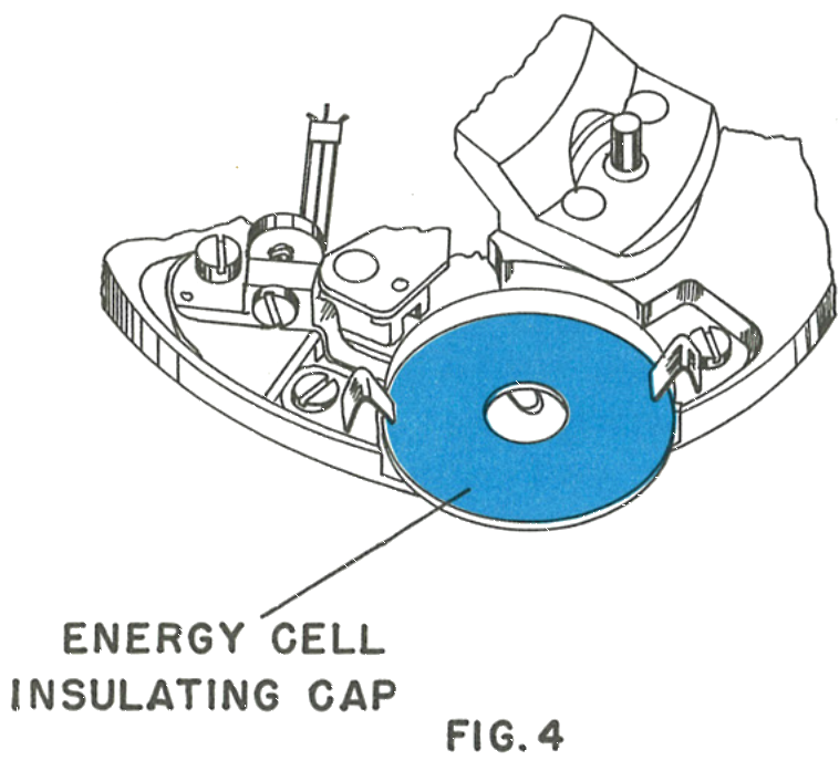
Before clamping the energy cell in position, make certain that the flat energy cell insulating cap is in position on the movement.
Fig. 67.4 · Figure 4
5 · The Holding Spring
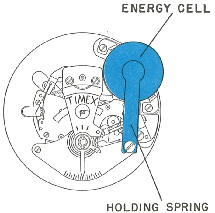
The energy cell should now be clamped to the movement by the use of a holding spring. The holding spring is available from the Timex Corporation and will be supplied upon request.
Fig. 67.4 · Figure 5
6 · The Current Path
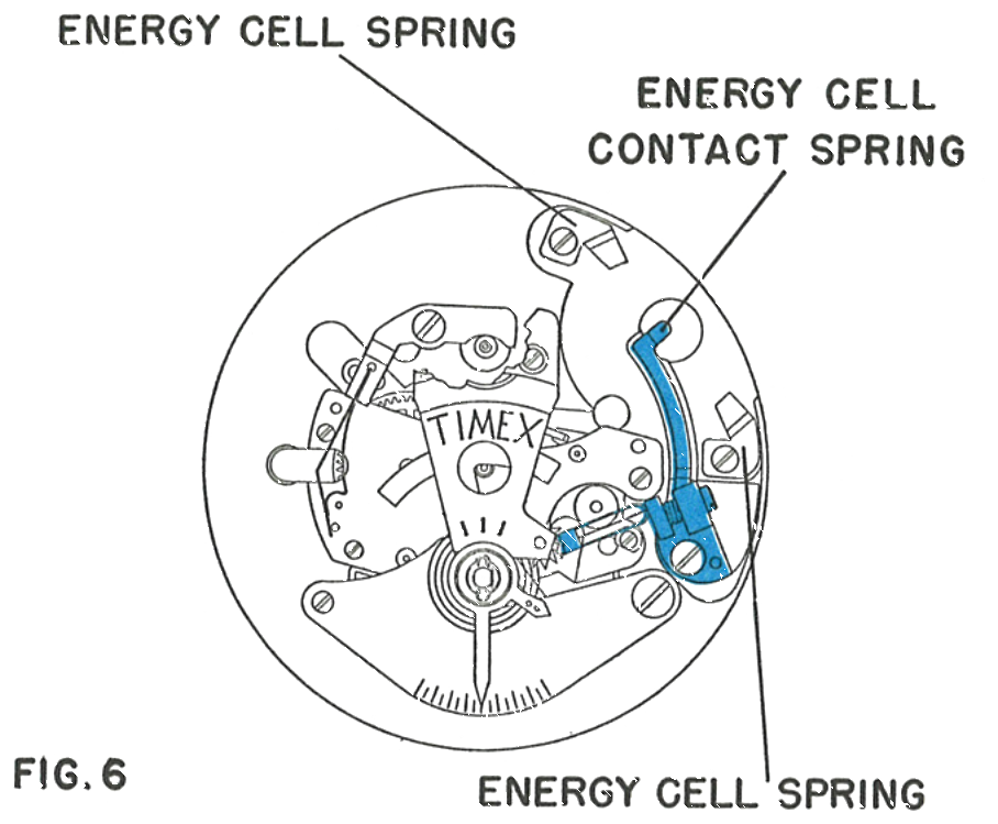
The negative pole of the energy cell must touch the energy cell contact spring, which is insulated from the plate. The positive pole, the metal case of the cell, must touch the two side energy cell springs which are connected to the plate.
For the caliber 860 movement the same procedures are used, except that the flat energy cell insulator and the two side energy cell springs are not present. Use the shaped plastic energy cell insulator between the movement and the negative pole to insulate the cell from the plate.
Caution: Never cause any metallic connection between the parts shown in blue and those in white. A temporary short circuit would result which could shorten the life of the cell.
Fig. 67.5 · Figure 6
For the caliber 860 the same procedures are used, except that the flat insulator and the two side springs are not present. Use the shaped plastic insulator between the movement and the negative pole.
The Contact Parts
1 · The Contact Closing
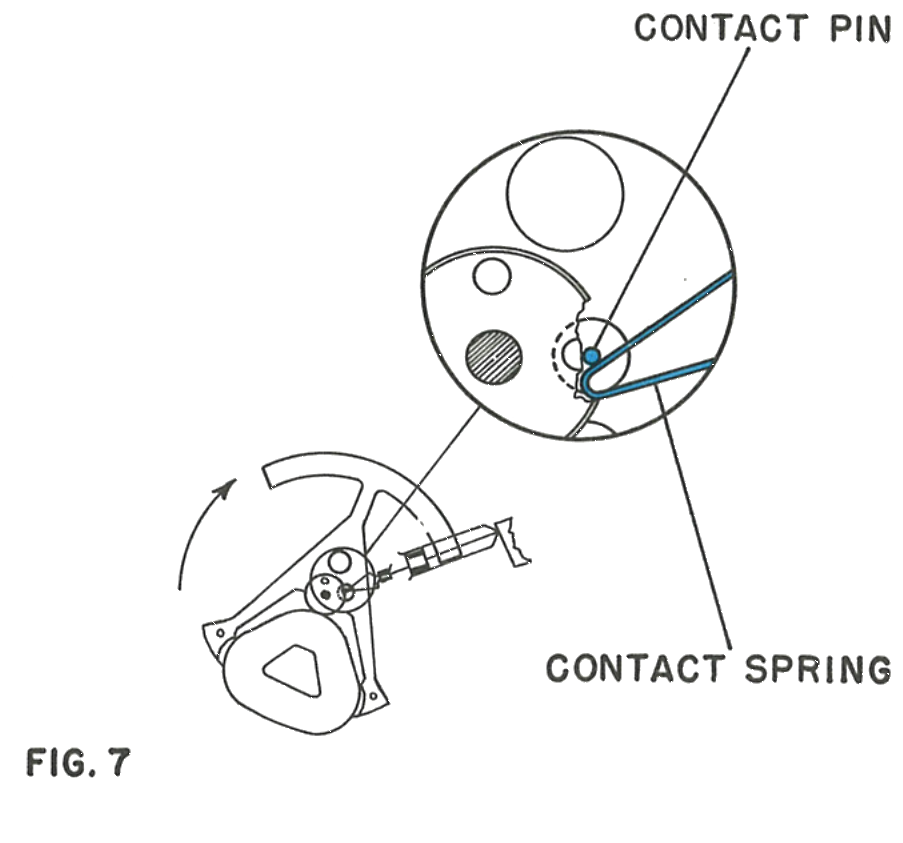
Rotate the balance slowly from its rest position with a clean brush. The instant the contact spring touches the contact pin, current flows through the balance drive coil. The current induces a magnetic field which opposes the field of the magnet, and this opposition imparts an impulse to the balance.
Fig. 67.5 · Figure 7
2 · The Return Stroke
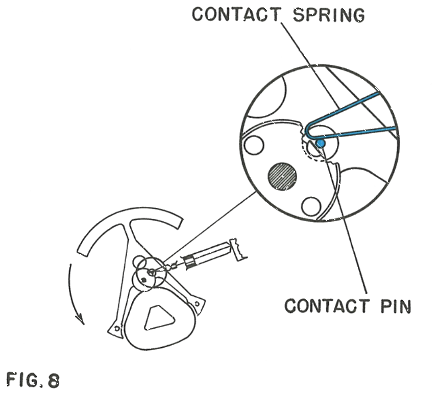
After the balance returns to its neutral position, the same process is repeated in the opposite direction. Repeat this test several times until the drive action is fully understood. The function of the remainder of the movement is fully mechanical.
Note: Before further work, remove the energy cell to prevent the possibility of a short circuit.
Fig. 67.5 · Figure 8
3 · The Contact Assembly
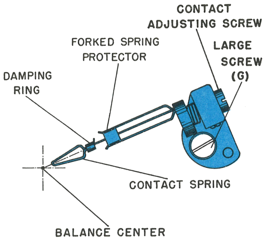
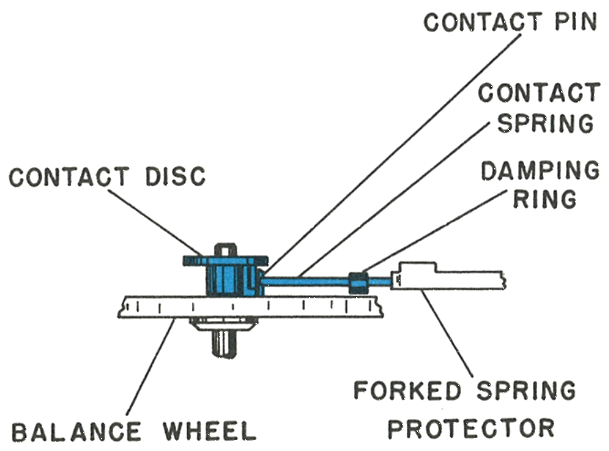
The contact spring must be pointing exactly to the centre of the balance staff. It should be centred horizontally between the contact disc and the balance. The forked spring protector should be adjusted so the contact spring is exactly in its centre.
Caution: The contact adjusting screw should not be turned. It has been fixed in the best position at the factory with a drop of epoxy resin.
Fig. 67.6 · Contact Parts
4 · The Contact Disc
After removing the large screw (G) and the insulating washer beneath it, remove the complete contact spring assembly together with the insulating plate. The loose damping ring and the spring protector need not be dismantled further.
You can now remove the balance cock and the balance.
Caution: The contact spring requires very careful treatment. Protect it from scratches and deforming, avoid excessive bending, and do not touch the contact area at the end of the spring. Handle it with the same care as a hairspring.
Fig. 67.6 · Contact Disc
5 · The Contact Pin and Jewel
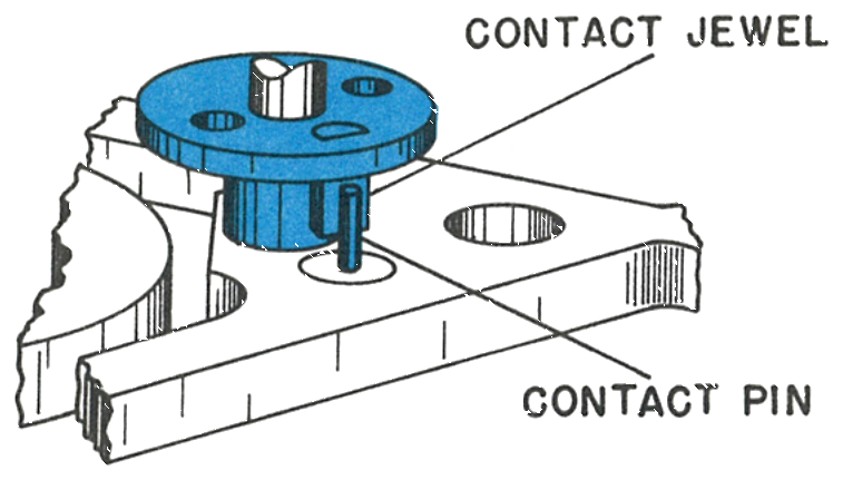
Treat the contact pin on the balance with the same delicacy afforded the contact spring. The contact pin is protected to a great extent by the contact jewel behind it and the contact disc located on top of it.
Fig. 67.6 · Contact Jewel
6 · The Overbanking Lever
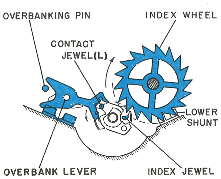
The caliber 861 incorporates an overbanking lever not used in the caliber 860. The lever is operated by the jewel (L) fixed on the balance assembly and is kept in place at its extremities by magnetic attraction.
The overbanking pin limits the amplitude of the overbanking lever in the same manner as a banking pin limits the amplitude of the pallet lever in a mechanical watch.
Fig. 67.6 · Overbanking Lever
Index & Sweep Second
The gear train is driven by the “D” shaped index jewel located on the balance. This jewel moves the index wheel one tooth at every second half oscillation of the balance.
1 · The Index Wheel at Rest
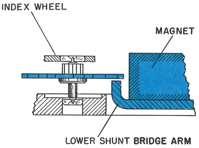
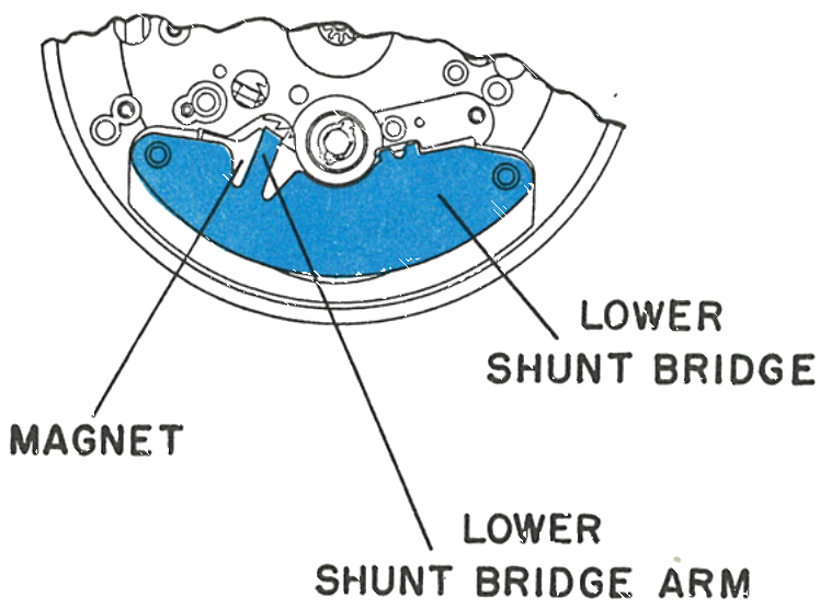
So long as the index jewel is not in contact with the index wheel, the index wheel is held in its rest position by magnetic attraction between it and the arm of the lower shunt. By rotating the index wheel slowly with a fine pointed cleaning stick, the driving action can be observed.
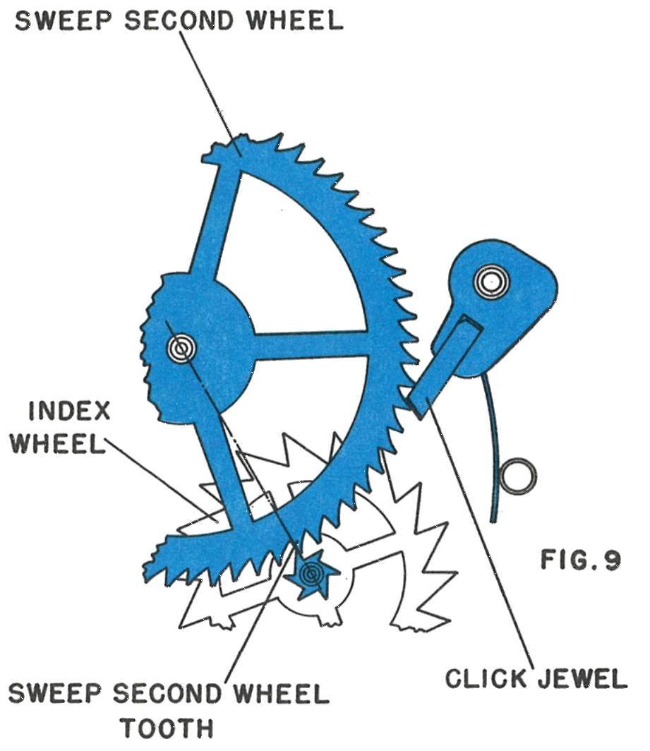
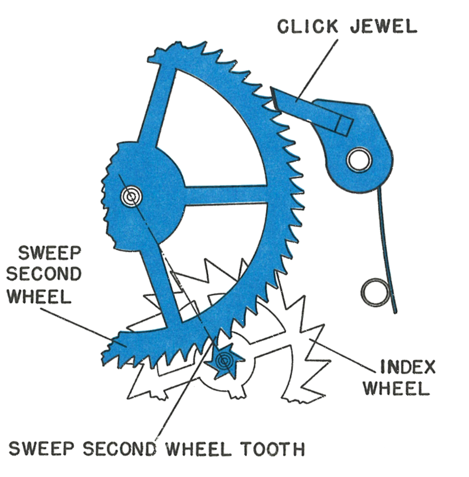
The sweep second wheel is moved one tooth at every third index of the index wheel. The gear arrangement serves to move the sweep second wheel between second jumps into a position where the straight side of the sweep second wheel tooth, next engaged by an indexing pinion tooth, is exactly on the centre line between the sweep second wheel centre and the index wheel centre. The face of the teeth on the index pinion also falls on the same centre line after every third indexing, and touches a sweep second wheel tooth.
To adjust the position of the index wheel, bend the lower shunt bridge arm. To adjust the position of the sweep second wheel, move the spring loaded click jewel. Two different click jewel arrangements have been used on the Model 67 movement.
Fig. 67.7 · Index Wheel
The sweep second wheel is moved one tooth at every third index. The gear arrangement places the straight side of the next-engaged sweep second wheel tooth exactly on the centre line between the sweep second wheel centre and the index wheel centre.
To adjust the index wheel, bend the lower shunt bridge arm. To adjust the sweep second wheel, move the spring loaded click jewel. Two different click jewel arrangements have been used.
2 · The Earlier Click Jewel
The type shown in figure 9 will be found on earlier Model 67 movements.
Fig. 67.7 · Figure 9
3 · The Later Click Jewel
The type shown in figure 10 will be found on the latest Model 67 movements.
Caution: The teeth in the index pinion are in precise alignment to the index wheel. Do not disturb this relationship, and do not increase the air gap between the index wheel and the lower shunt arm. If the click jewel is adjusted, the tension of the click should not be changed.
Fig. 67.7 · Figure 10
Hand Setting
1 · The Set Spring and Stopping Spring
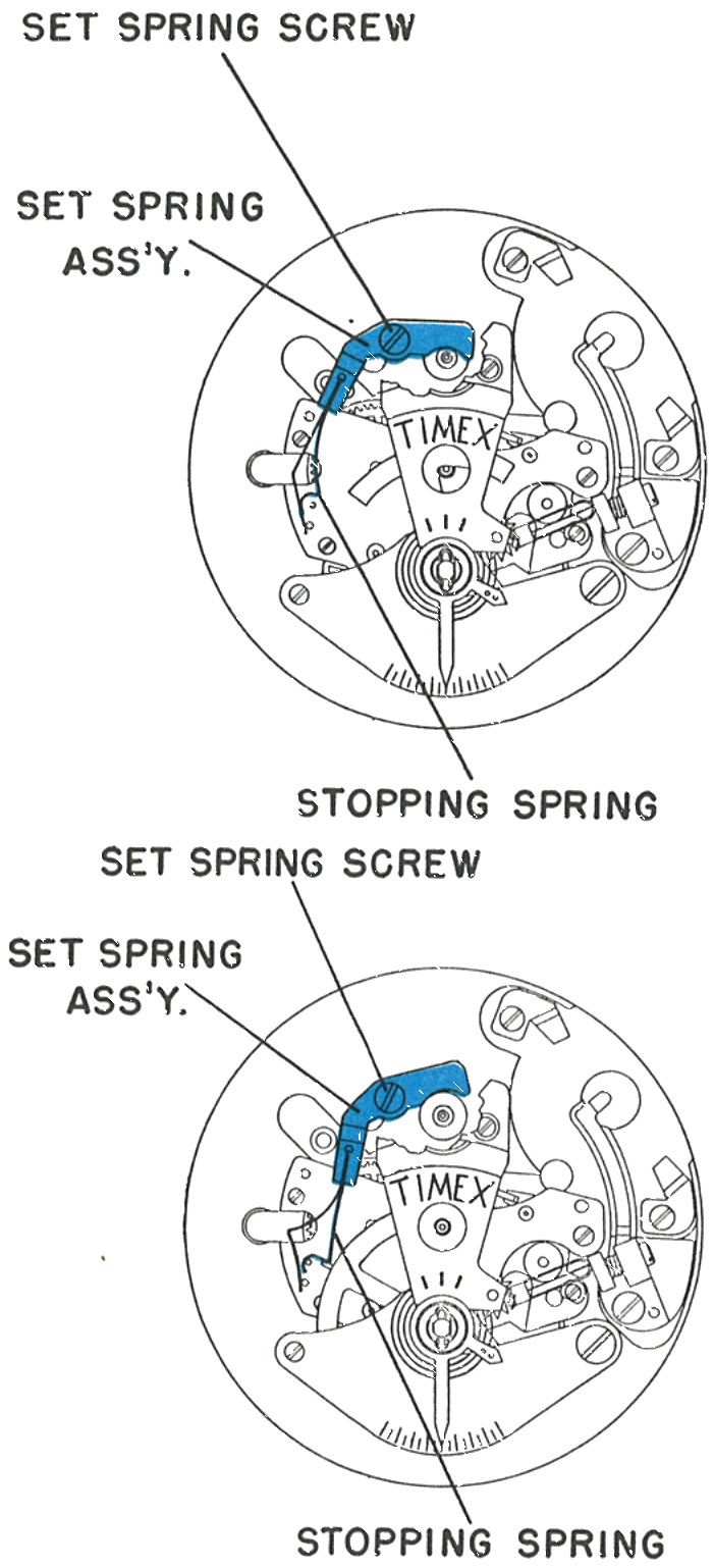
The balance stopping arrangement should be adjusted so that the stopping spring contacts the balance stopping pin only when the setting wheel located on the caseback is pulled out.
Note: The balance stop lever holding screw has a left hand thread.
Fig. 67.8 · Set Spring
2 · What Stays on the Plate
After removal of the set spring assembly and the other parts, only the magnet and the lower shunt bridge remain on the movement.
Caution: Make no attempt to remove these parts from the plate.
Fig. 67.8 · Lower Shunt Bridge
Cleaning & Lubrication
Lubricant change, June 1974: Timex Service Bulletin No. 111 replaced the factory oil for this model. Moebius Synt-A-Lube oil is used instead of Elgin M56B oil. (It supersedes Bulletin No. 108.)
1. The movement may now be cleaned in the usual method using normal watch cleaning and rinsing solutions. The balance and contacts must be cleaned very carefully using only new and clean solutions. Do not clean the energy cell with any liquid; if necessary it should be wiped with a dry cloth only.
2. After cleaning, any particles adhering to the magnet should be carefully removed. A piece of scotch tape rolled to a point will be found useful. This process should not be used when the movement is assembled, as there is danger of severing the lead wires of the balance coil. The other parts of the movement must be free of particles, especially steel or nickel which would be attracted by the magnet.
3. Lubricate the jewelled bearings and pivots of the train wheels and balance when assembling. In addition, the bearings and pivots of the overbanking lever and dial train should be lubricated. The remainder of the non-jewelled wheel bearings require no lubrication, as the gear train is not stressed.
Oil the spring loaded pawl jewel on the sweep second wheel so the teeth become covered with a thin oil film. Lubricate the bearing surface of the balance stop lever at the screw, the conical part of the setting stem, and the bearing of the setting stem in the balance cock.
Caution: Never lubricate the contact pin on the balance, the contact spring assembly including the spring and damping ring, the index jewel, or the teeth of the index wheel. Since the watch contains permanent magnets, no attempt should be made to demagnetize it.
4. The Timex electric achieves its best running results if the hairspring does not vibrate within the regulator slot. The outside edge of the hairspring should be in light permanent contact with the inside edge of the regulator key. This adjustment should not be changed.
Reading the rate recorder: Waved lines with a period of 6 seconds and a double printed line do NOT indicate poor balance amplitude with this type of watch. They are typical of watches with direct gearing between balance and train wheels and have no influence on timekeeping. The average inclination of the pattern line indicates the rate.
This guide is based on the original Timex factory service manual for the Model 67 movement.