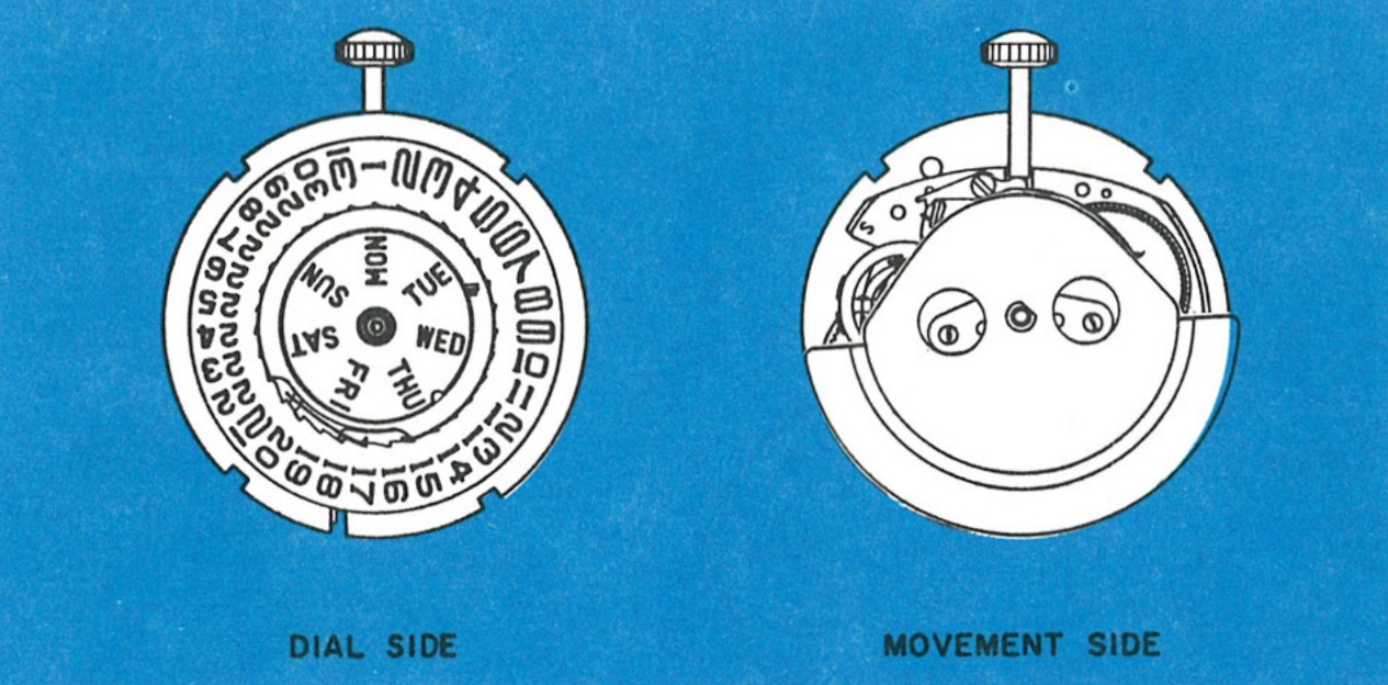
A Day & Date Self-Winder
The Model 33 movement is a 13 ligne self-winding movement with day and date features. The Model 33 utilizes the same basic construction as the Model 31 except that a day and date mechanism has been added. A planetary gear winding system located on the front frame provides the same gear reduction.
The reserve power of the mainspring, when the watch is worn by a normally active person, is sufficient to run the watch for a full day. The day and date mechanism is similar to that used in the Model 27.
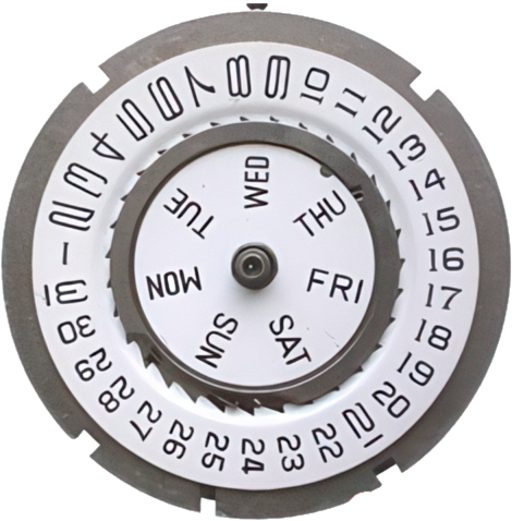
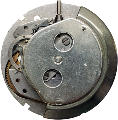
Exploded View
For the movement underneath, see the Model 31 exploded view.
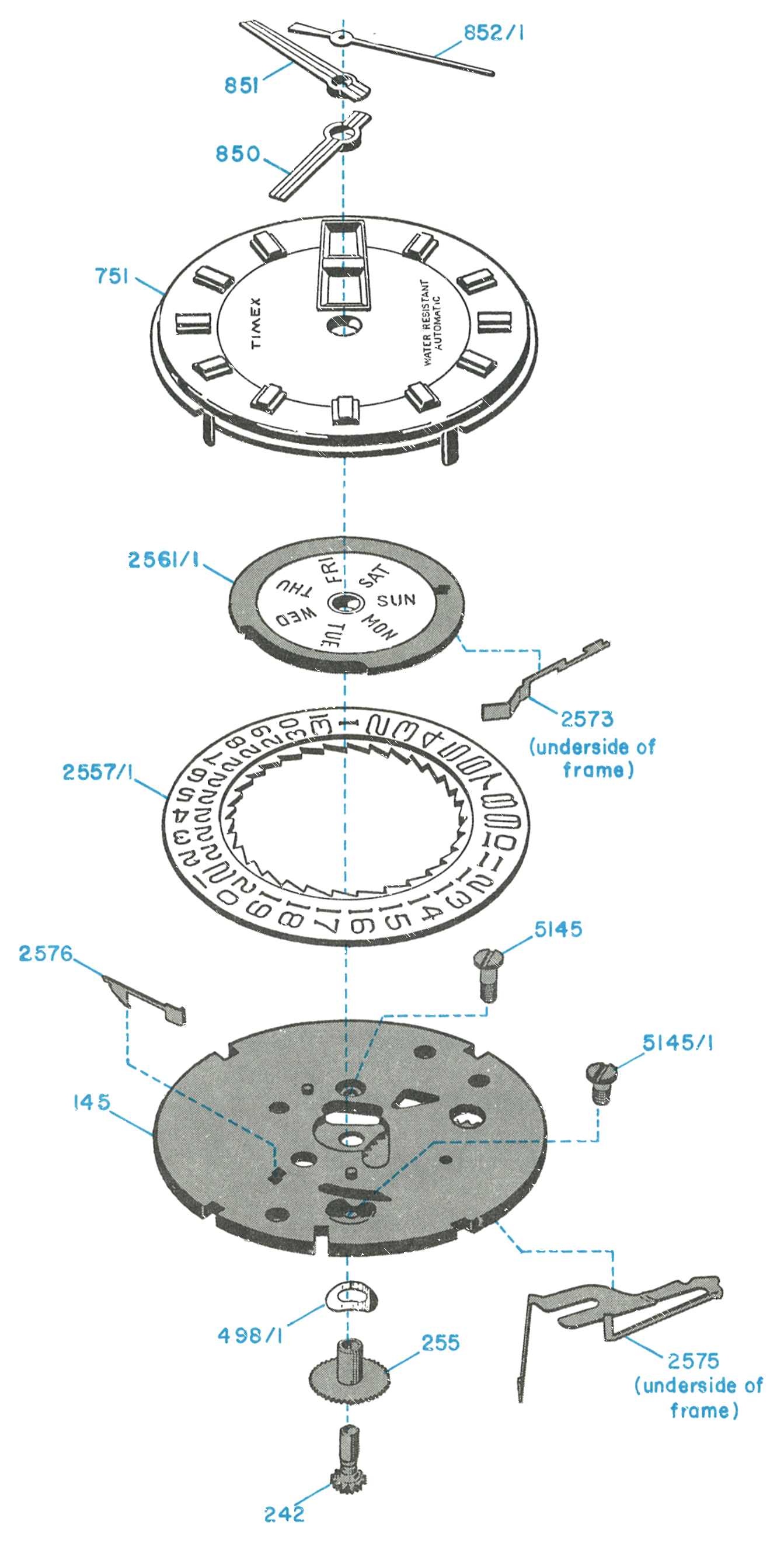
Disassembly
Removing the Rotor
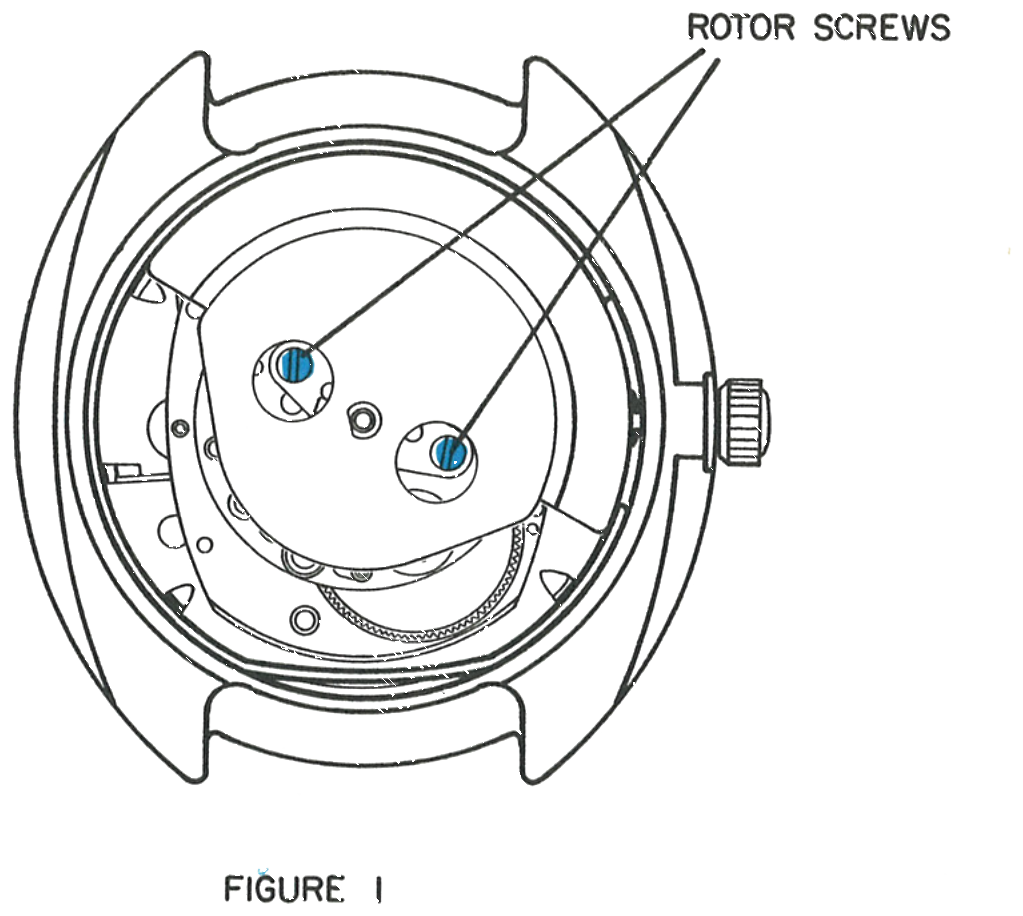
Remove the case back. Loosen and remove the two rotor frame screws.
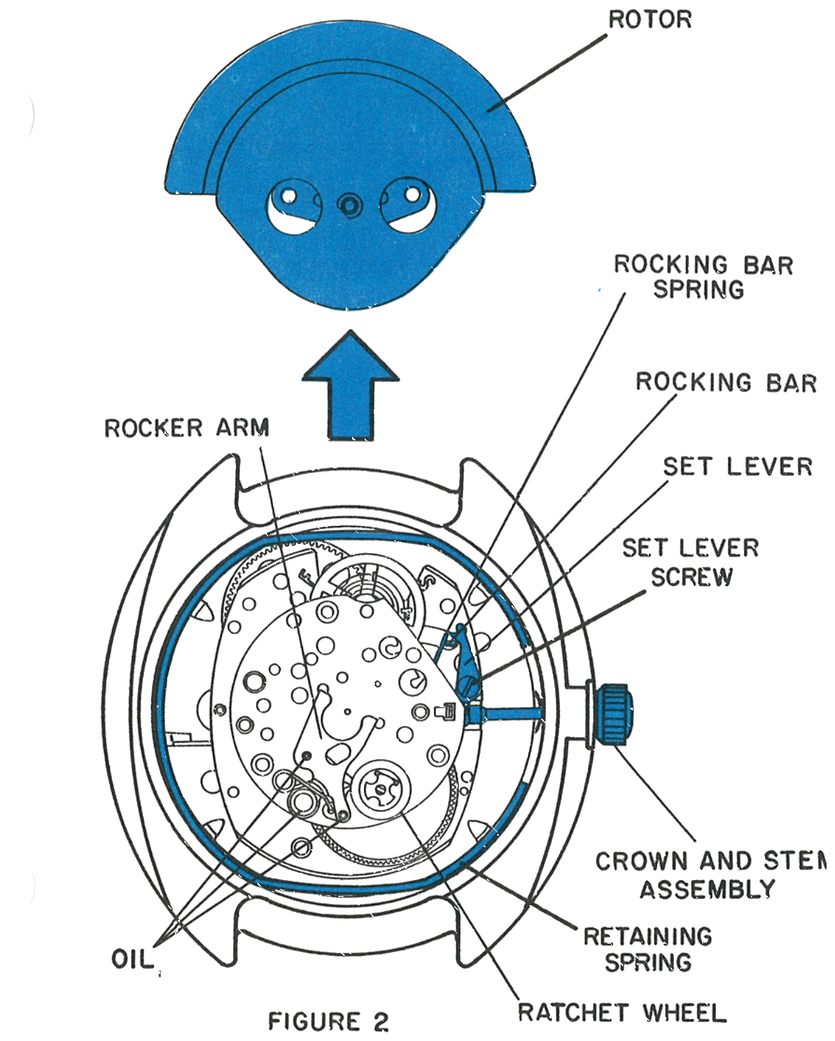
Lift the rotor assembly slightly to free the dowels. Since the rocker arm fits between the rotor frame and the rotor weight, position the rotor weight as shown in figure 2 and slide the assembly along the movement plate, toward the balance wheel, until it is free of the rocker arm. Then lift the assembly out of the case.
Removing the Crown, Stem and Dial
Pull the crown out into the set position. Loosen the set lever screw and raise the lever sufficiently to release the stem, then pull the crown and stem assembly free of the movement and the case.
With tweezers, carefully remove the retaining spring from the bezel. Be careful not to damage the balance wheel assembly.
Carefully turn the watch over and the dial and movement assembly will fall out. Replace the crown and stem assembly and retighten the set lever screw.
Remove all hands. Turn the assembly over and bend the four dial tabs sufficiently to free the dial from the date frame. Hold the dial in place and turn the assembly so the dial is up, then carefully lift the dial off the movement. Note the positions of the parts under the dial.
Day & Date Mechanism
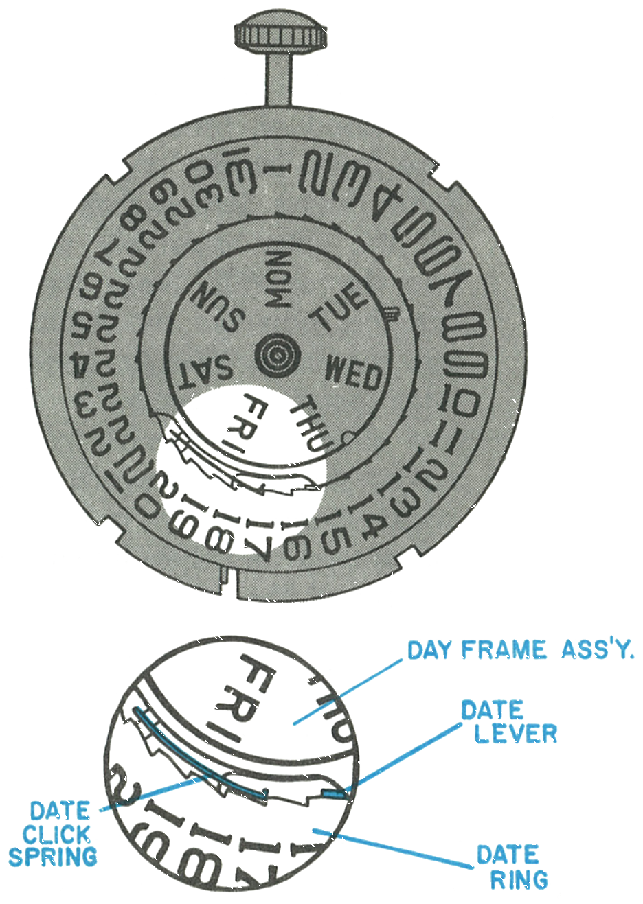
Date Ring Indexing
A tab on the underside of the date wheel engages the date lever and moves the date lever tab backward one tooth on the date ring.
At a predetermined time, about midnight, the date lever is released and moves the date ring forward one space. The date click spring engages the date ring to prevent backward motion when the date lever is being moved.
Day Dial Indexing
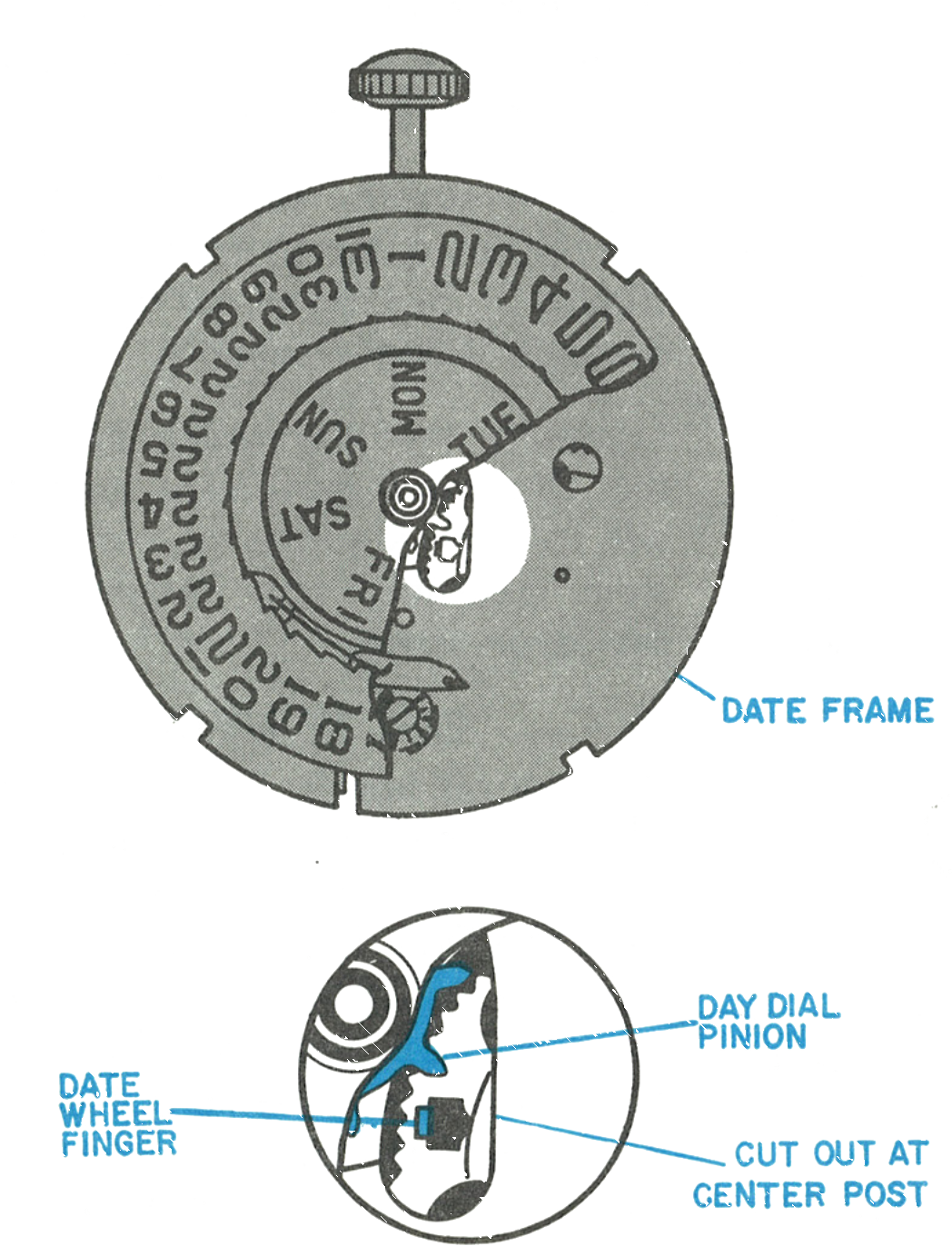
A tab on the upper side of the date wheel engages the day dial pinion.
Rotating the day dial pinion moves the day dial forward one position at about 1 o’clock in the morning. The day detent spring positions the day dial.
The Planetary Gear and the Mainspring
Turn the movement over and, with tweezers, lift the end of the rocking bar spring free from the end of the rocking bar.
Turn the movement over so the date frame is up and remove the two pillar screws. Lift the date frame assembly off the movement, being careful not to disturb loose parts underneath. Replace the long pillar screw in the rocking bar on the movement.
Lift off the hour wheel washer, hour wheel and cannon pinion assembly.
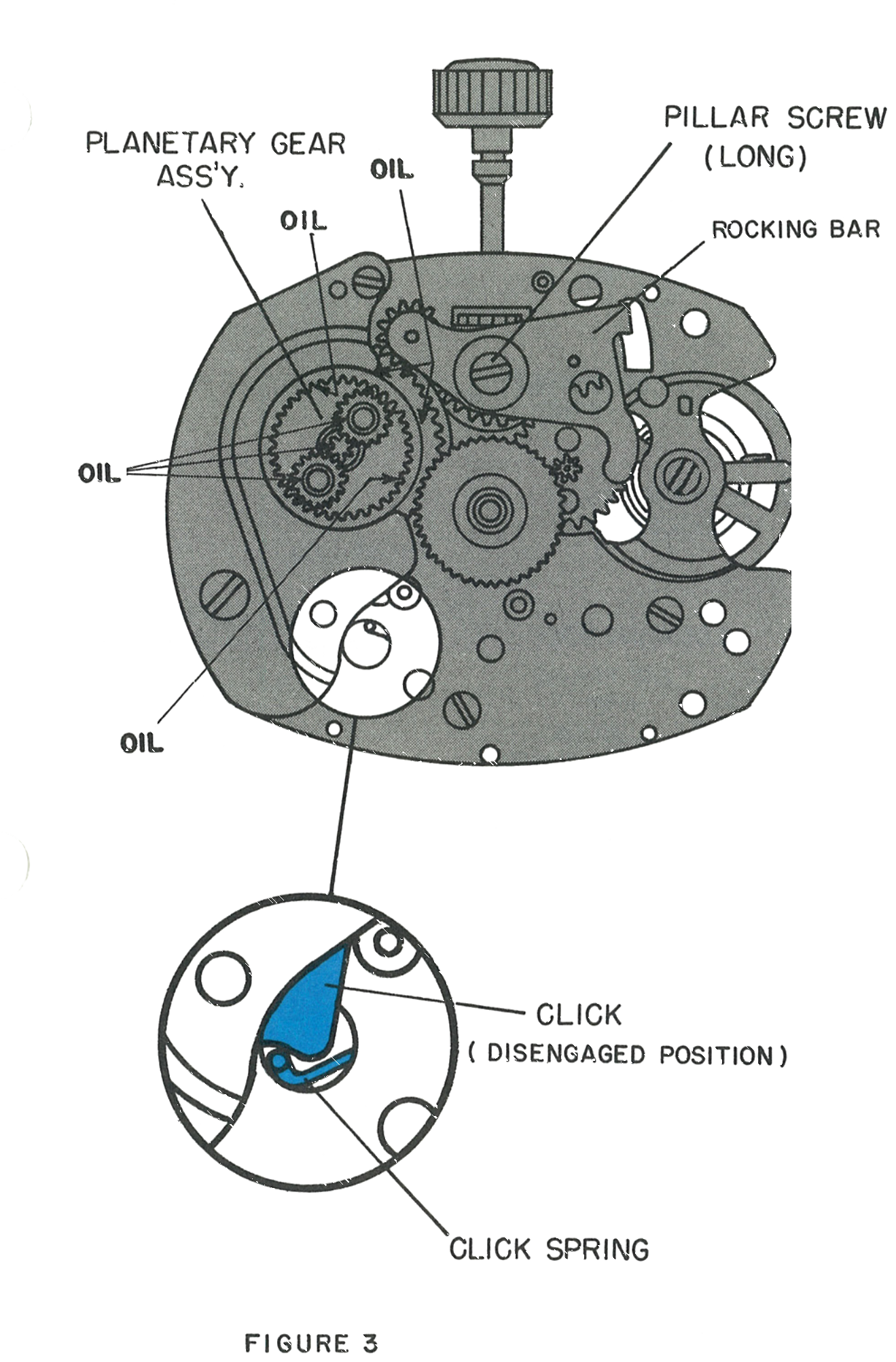
The stored power must be released from the mainspring in order to service the movement. For reference purposes, the click in this movement is partially hidden by the plate which holds the planet gear assembly in position. There is no need to remove the planetary gear assembly from the frame of the movement assembly.
Cleaning & Lubrication
The Model 24 procedure for removing the balance, cleaning, lubricating and reassembling the balance, described on pages 24.5, 24.6 and 24.7, should be followed for the Model 33 movement. The basic movement must be lubricated as described for the Model 24 on page 24.6, with Elgin M56b oil used in the factory.
Beyond that, three additions are not illustrated here: Moebius Special Lubricant #206 on the outside surface of the rotor cam, forced beneath the rotor staff head and between the rotor frame and the rotor cam; fine watch oil on the ratchet wheel teeth and the three pivot points shown in figure 2; and fine watch oil on the seven bearing points of the planetary gear system noted on figure 3. The three below are illustrated.
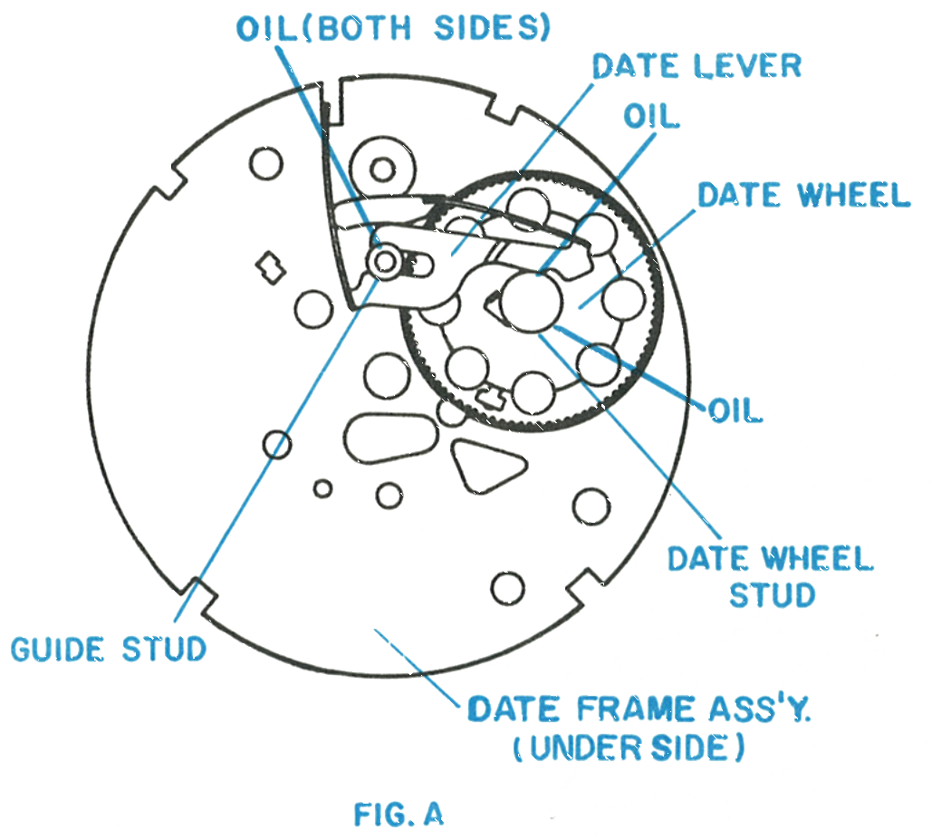
Date Lever and Date Wheel Stud
Lubricate the junction of the date lever with the date wheel stud, both sides of the junction of the date lever with the guide stud, and the bearing between the date wheel and the date wheel stud.
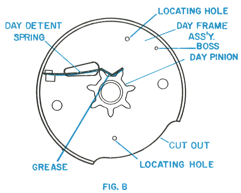
Day Detent Spring
Apply a coating of grease, Hamilton PML in the factory, to the junction of the day detent spring and the day pinion.
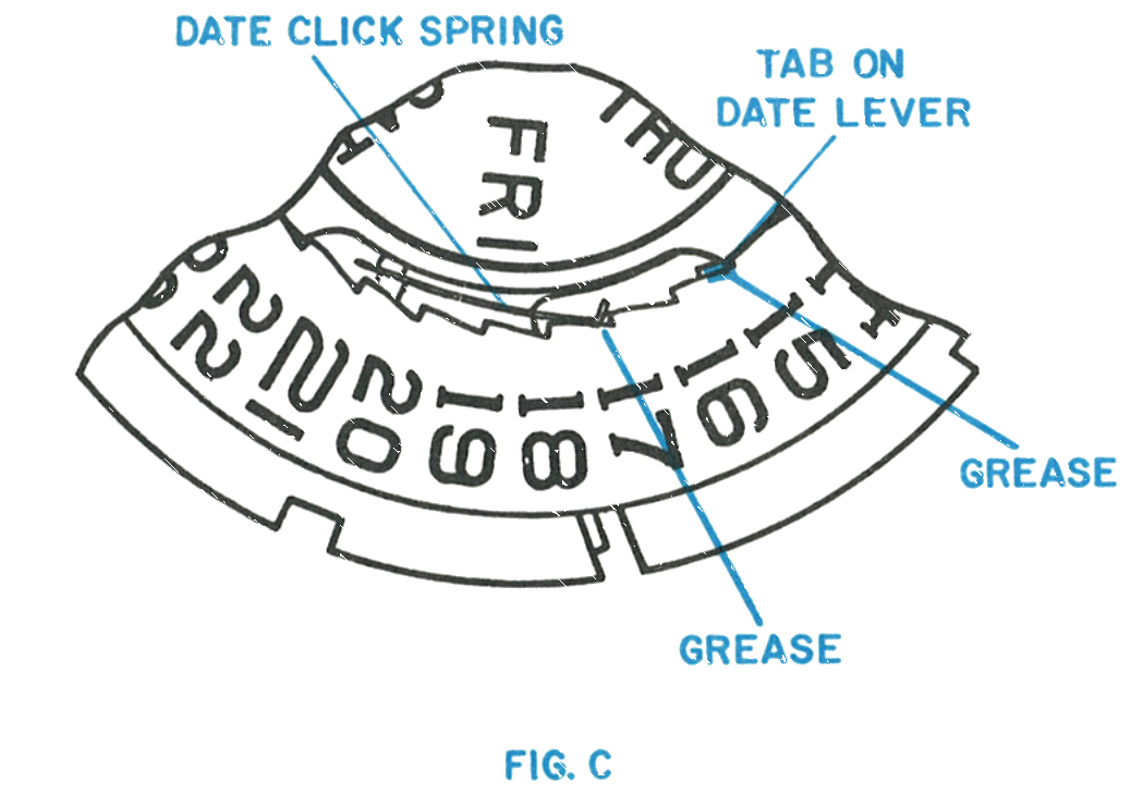
Date Click Spring
Apply a coating of grease, Hamilton PML in the factory, to the junction of the date click spring with the teeth of the date ring, and to the junction of the tab on the date lever with the teeth of the date ring.
Reassembly
Reassembling the Movement
Assemble the cannon pinion assembly onto the centre post of the movement. Apply a small amount of fine watch oil to the centre hole in the cannon pinion. Assemble the hour wheel and hour wheel washer onto the cannon pinion assembly.
Remove the short pillar screw, if assembled, and the long pillar screw from the movement. Be sure the bushing is in place in the rocking bar, then position the lubricated date frame assembly on the movement. Hold the date frame assembly in place and check proper date wheel engagement by testing with tweezers.
Secure the date frame assembly to the movement with the long and short pillar screws. Reengage the rocking bar spring as shown in figure 2. Check for proper engagement and function of the crown and stem assembly. Rotate the crown enough to move the finger on the date wheel away from the cut out at the centre post.
Position the date ring on the date frame so it is engaged with the finger on the date lever and the detent spring. Test the lubricated day frame assembly for free rotation of the day pinion against the day detent spring, then position it over the centre of the movement and orient it on the date ring so the left end of the cut out just clears the tab on the date lever. Apply light pressure and move the day frame assembly slightly until the two holes and boss seat on the corresponding bosses and hole in the date frame assembly. Centralize the date ring under the day frame assembly.
Carefully orient the dial over the assembly and then, holding the dial in place, turn the assembly over and bend the four tabs to secure the dial to the date frame.
Positioning the Hands for Proper Day and Date Change
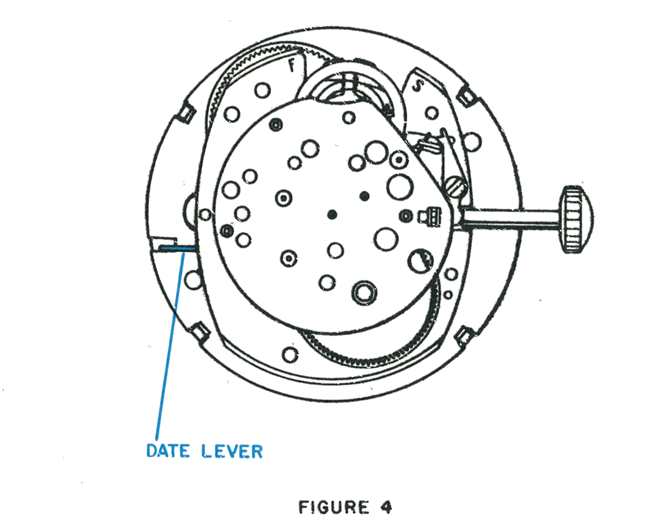
Hold the watch assembly with the movement side up and the crown and stem at the three o’clock position. Pull out the crown and stem.
Rotate the crown and stem slowly and observe the date lever at the nine o’clock position. The date lever will begin to move and a click will be heard. After the click, rotate the crown slowly until the date lever snaps back, then stop rotating.
Turn the assembly over and replace all hands at the 12 o’clock position. Check the proper function of the day and the date change mechanism.
Loosen the set lever screw and remove the crown and stem. Position the dial and movement assembly in the bezel, insert the crown and stem through the bezel and retighten the set lever screw.
Reassemble the retaining spring as shown in figure 2. The end of the spring should be inserted into the groove near the stem at the balance wheel end of the movement. Insert the rest of the spring into the groove, being careful not to damage the balance assembly.
Reassemble the rotor assembly by sliding it into the movement under the rocker arm as shown in figure 2. Secure the rotor to the movement with two screws as shown in figure 1. Position the case back with the “T” on “Timex” toward the crown and snap it into the bezel.