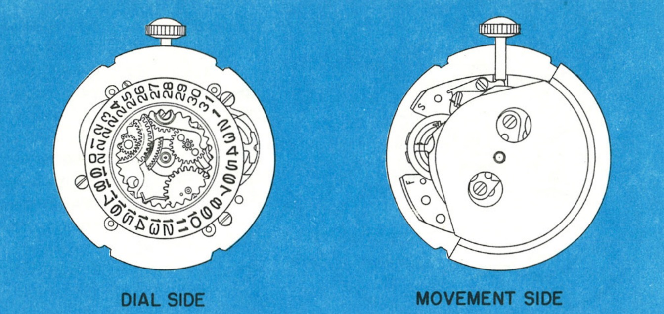
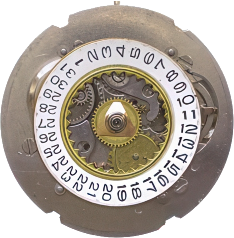
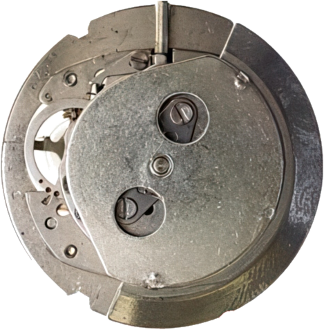
A thin self-winding calendar watch built on the construction of the Model 24, with a planetary gear winding system on the dial plate and a calendar mechanism taken from the Model 25.
Self-WindingCalendar13 LigneModel 24 Base
Factory Service Manual · Model 32 · Dial Side & Movement Side
Ligne13
Diameter29.08 mm
Diameter (inches)1.145 in
TypeSelf-winding calendar
Built onModel 24 construction
CalendarAs Model 25
ManualService Manual · Model 32
Height6.00 mm
Jewels0
EscapementPin lever
Beat rate18,000 bph
Power reserve38 h
Height, jewels, escapement, beat rate and power reserve: ranfft.org
A Self-Winding Calendar
The TIMEX Model 32 movement is a new thin self-winding calendar watch utilizing the basic construction of the Model 24. A planetary gear winding system located on the dial plate provides a compact method of obtaining the necessary gear reduction between the self-winding weight and the mainspring.
The reserve power of the mainspring, when the watch is worn by a normally active person, is sufficient to run the watch for a full day. The calendar mechanism is similar to that used in the Model 25.
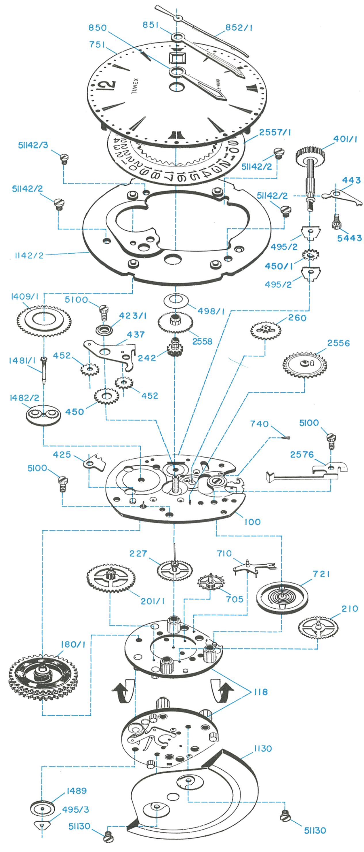
Timex found that the best method of cleaning is with only the sweep second hand, dial, date ring, date wheel assembly, rotor, mounting ring, planetary gear system and balance removed. The cleaning fluid, while removing any contamination from the movement, will also remove oil from the gear train, pivots and holes.
Note: If further dismantling is required, follow the instructions for the Model 25 movement.
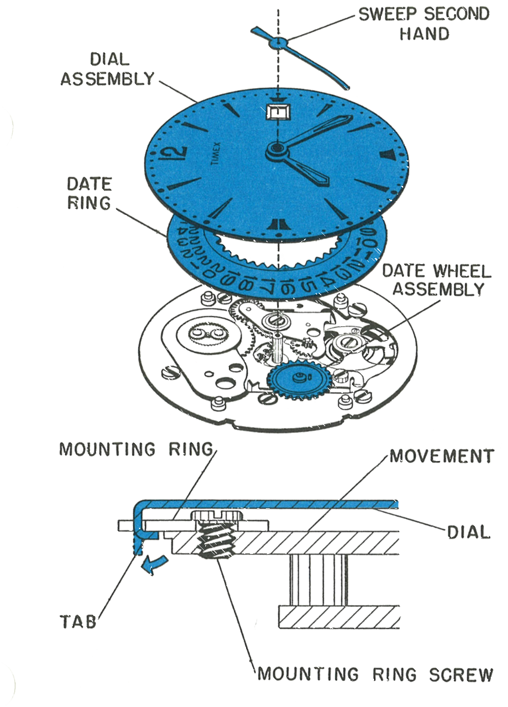
1 · Removing the Dial, Date Ring, Date Wheel Assembly and Hands
Remove the sweep second hand. Do not remove the minute or hour hand.
The dial is clamped to the movement mounting ring by four tabs protruding from the outside of the dial. Straighten these tabs as indicated by the arrow and dotted lines in the illustration and remove the entire dial assembly.
Once the dial is off the movement, the date ring and date wheel assembly can be removed. There is no need for further disassembly of the dial assembly for cleaning unless severe contamination is present on the friction and cannon pinions. Should further disassembly be necessary, removal of the minute hand will free the friction and cannon pinion assembly. The friction pinion is held in the cannon pinion by a snap fit.
Fig. 32.3 · Dial, date ring & hands
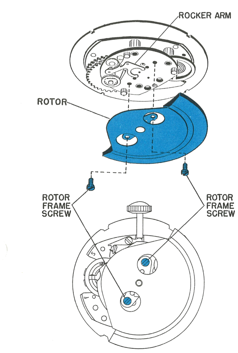
2 · Removing the Rotor
Invert the movement so that the movement plate is facing you and remove the two rotor frame screws.
Lift the rotor assembly slightly to free the dowels which position it. Since the rocker arm fits between the rotor frame and the rotor weight assembly, the rotor weight must be removed by sliding it along the movement plate until it is free of the rocker arm.
Caution: Any attempt to lift the weight before it is free of the rocker arm will result in damage to the movement.
Fig. 32.3 · Removing the rotor
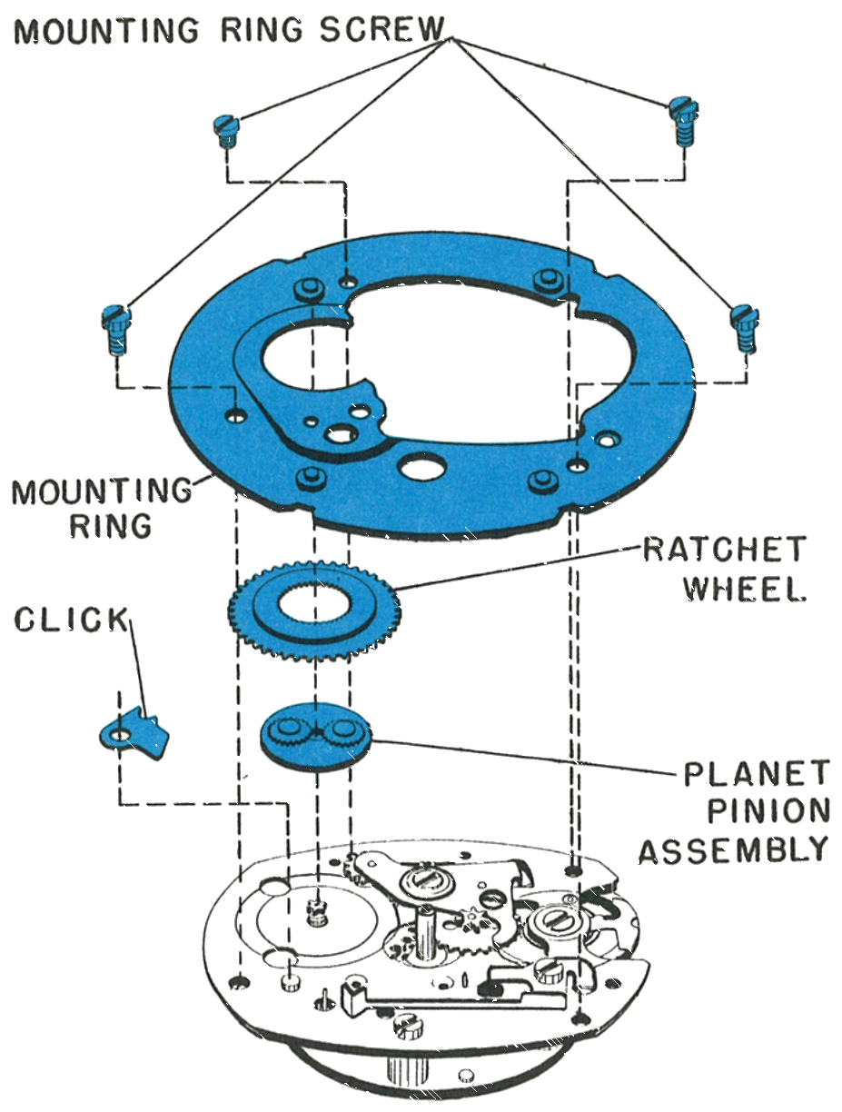
3 · Removing the Mounting Ring
Before removal of the mounting ring, the mainspring power must be fully let down. Grasp the crown in the fingers of one hand and move the click out of engagement with the ratchet wheel. Let the crown revolve slowly in the fingers, being careful not to let the crown slip.
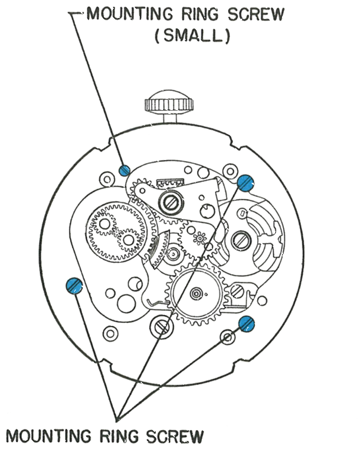
After letting the power of the mainspring down, remove the four mounting ring screws. Next remove the mounting ring, ratchet wheel, planet pinion assembly and click.
Fig. 32.4 · Removing the mounting ring
4 · Crown, Stem and Balance Wheel
For the crown and stem, proceed as directed on page 25.4 for the Model 25 movement.
For the balance wheel, proceed as directed on page 25.5 for the Model 25 movement.
Fig. 32.4 · Mounting ring screws
Cleaning & Lubrication
Lubricant change, June 1974: Timex Service Bulletin No. 111 replaced the factory oil for this model. Moebius Synt-A-Lube oil is used instead of Elgin M56B oil or Tenneco #415 oil. (It supersedes Bulletin No. 108.)
After disassembly of the sweep second hand, dial, date ring, date wheel assembly, rotor, mounting ring, planetary gear system, click and balance, the movement is ready to be cleaned. The same instructions for cleaning as given for the Model 25 movement apply to the Model 32. Care should be exercised to insure complete cleaning of all self-winding parts.
The same reoiling instructions given for the Model 25 movement apply to the Model 32. In addition, all moving parts of the self-winding and planetary gear system should be lubricated.
Caution: As noted on the Model 25 movement, the mainspring is permanently lubricated and should not be oiled.
Reassembly
Use the disassembly procedures for the Model 32 and 25 movements as a guide for reassembly. Reassembly procedures for the balance wheel and positioning of the hairspring are given on page 25.7. Procedures for date mechanism reassembly and positioning of the sweep second hand are given on page 25.8.
Helpful Hints
Oiling. When oiling the movement plate balance cup, to facilitate the precise entry of the oil to the bottom of the cup, insert the oiler through the dial plate balance screw hole before the balance screw is assembled.
A drop of oil applied to both sides of the stem wind pinion before assembly will hold the pinion and its bridges together, thus facilitating assembly, should complete dismantling of the movement be necessary.
Examine the action of the rotor on the winding frame. Be certain the staking is secure and that the rotor is free to make a complete revolution without interference. Check that the spring which holds the movement in the bezel is properly located in the groove in the bezel.
Check the freeness of the rocker arm and the clicks which are attached to it. Check that the yoke of the rocker arm slides freely on the cam attached to the self-wind weight without interference.
Check the action of the winding ratchet wheel. Each rotation of the rotor should move this wheel forward approximately 6 teeth.
Check the action of the mainspring and the barrel. The mainspring should have 5 to 6 full turns before the sliding tail begins to revolve in the barrel.
This guide is based on the original Timex factory service manual for the Model 32 movement.