The Two-Plate Design
The Timex movement is of two plate design, whereas most conventional watches feature the bridge design. The two plate design is most important as it ensures interchangeable accuracy for gear train and escapement: no further adjustment of escapement is necessary, and the correct locking engagement between pallet pins and escape wheel is ensured, thereby facilitating servicing. The use of individual bridges may require selective fitting and special adjustments.
It is necessary only to remove the balance wheel assembly, cannon pinion, ratchet wheel bridge, ratchet wheel and click. It is seldom necessary to remove other parts except those mentioned. However, these parts must always be removed for movement cleaning.
“Timex has found through long and careful research the best method of cleaning the movement is with only the forementioned parts removed (i.e. with barrel and mainspring in place).”
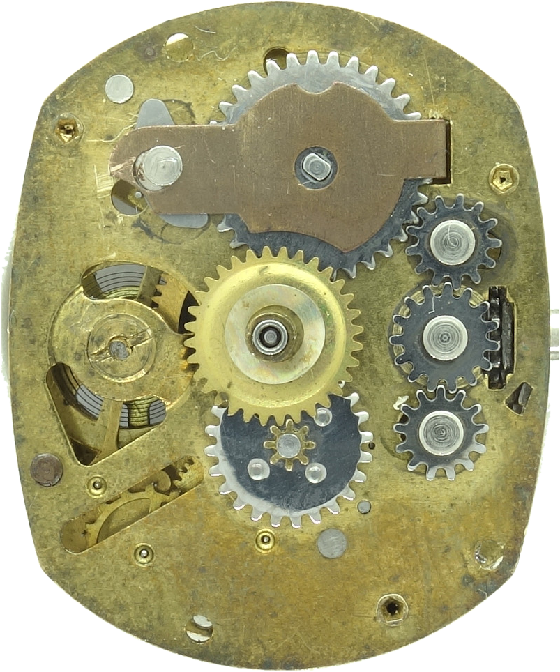
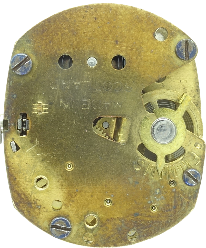
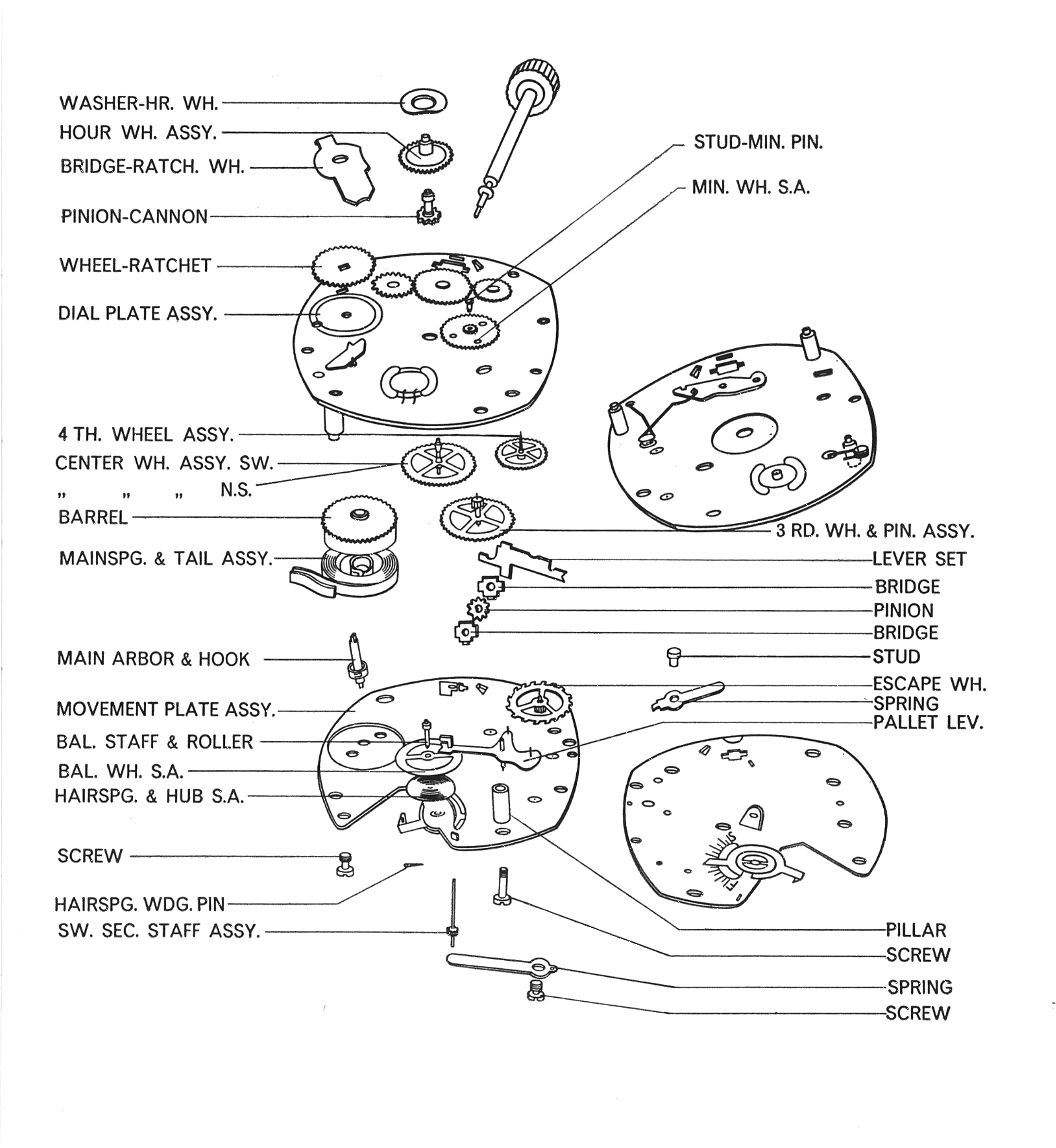
Exploded Views
Plates I, XIII and XI, the three calibres covered by this manual.


Disassembly for Cleaning
Removing Crown and Stem
On some models the winding stem must be removed before the movement can be taken out of the bezel.
This is easily done with any pointed instrument, preferably a pair of tweezers, brought down under the set lever just above the winding stem and pressed gently upwards, thereby releasing the stem.

Dust Seal Location
On newer non-waterproof models the dust seals shown are used. Type “A” is a formed metal seal with a bent lug. After being fitted to the winding stem, the bent lug should lie flat on the top face of the dial plate and the body of the seal placed between the caseback and bezel.
Type “A1” is the same as type “A” except that the bent lug has been eliminated. It fits exactly the way type “A” fits, except that the chamfered end should lie toward 12 o’clock.

Remove Dial and Movement Assembly
When removing the dial and movement assembly, insert the tweezers in the embossing on the dial holder.

Release Power from the Mainspring
The power of the mainspring should next be released. The crown should be held tightly between the index finger and thumb of the right hand, while with the left thumbnail the click is released.
The crown should be allowed to revolve slowly between the two fingers of the right hand until the power of the spring is completely released.

Removing the Balance Wheel
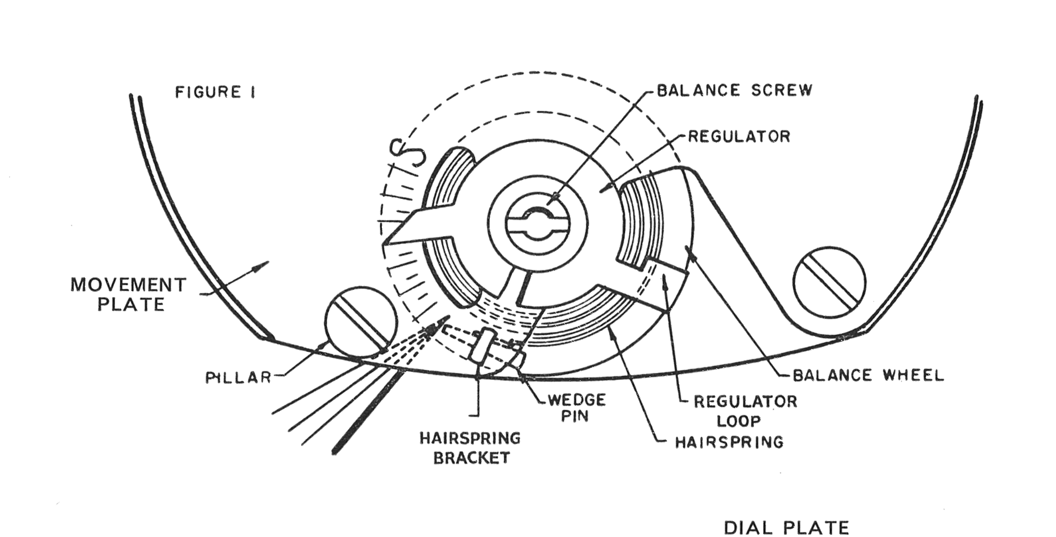
The small wedge pin holding the hairspring anchored to the bracket in the movement plate should be loosened and removed.
Figure I shows the complete operation of removal, by inserting tweezers between the dial plate and the movement plate using the tubular pillar as a support for the tweezers.
Pallet Lever & Escape Wheel
Change Balance Wheel
By carefully turning the balance wheel in the arrow direction, it should be checked that the hairspring is freed from its contact with the hairspring bracket and regulator.
The balance screw should then be unscrewed, using a screwdriver with a blade to fit the full length and breadth of the slot.

Removing Pallet Lever and Escape Wheel
The first operation is to unscrew the solid pillar screw and the tubular pillar screw, then remove the tubular pillar.
It is also important to loosen the opposite solid pillar screw by about a quarter turn. This gives less chance of distorting the movement plate during parts removal.
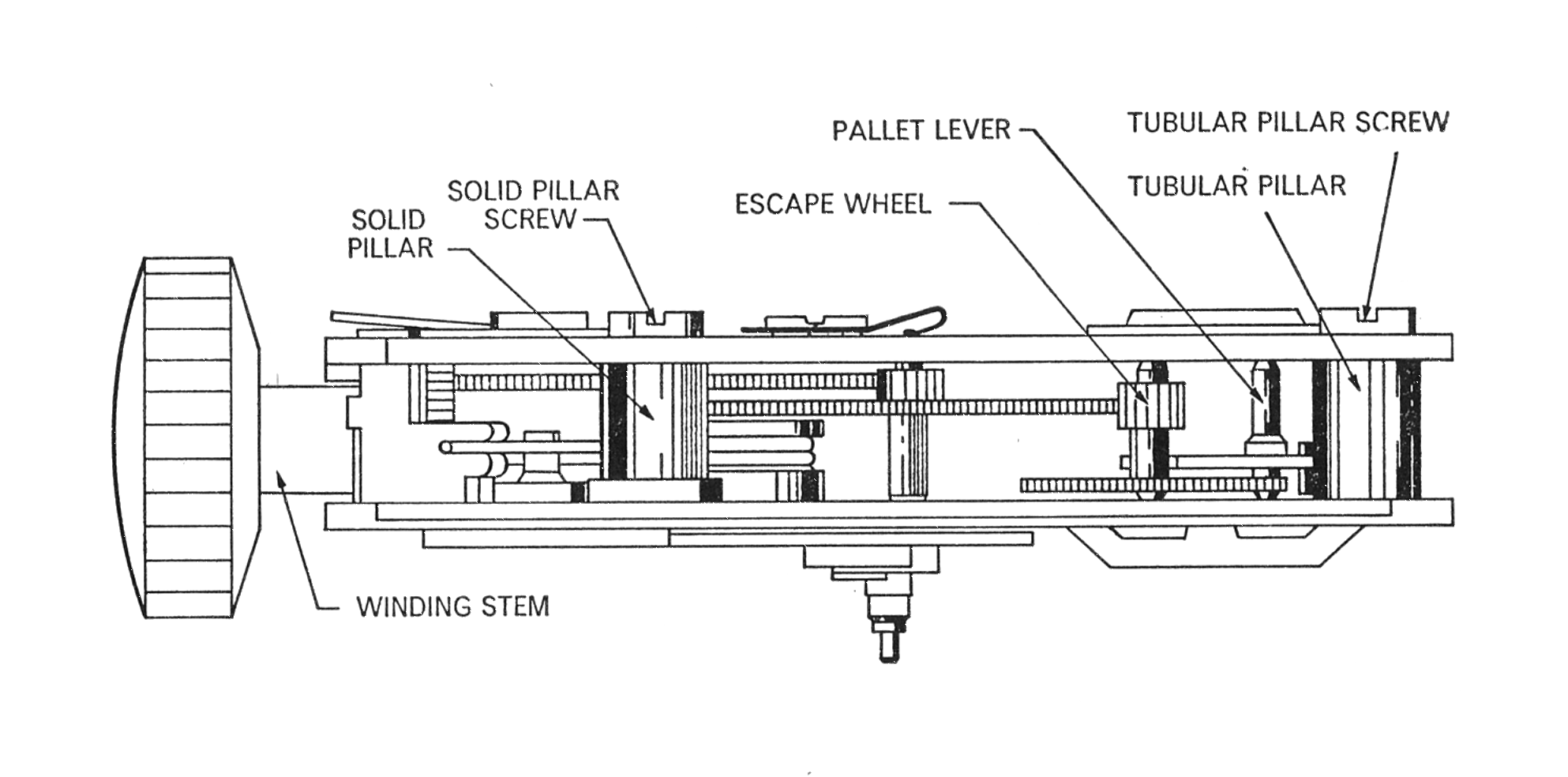
Changing Pallet Lever and Escape Wheel
When the escape wheel and pallet lever are released from their location holes, the parts are ready for removal. Tweezers are carefully inserted between the spread plates to hold the upper part of the pallet staff.
On replacement the escape wheel is inserted first, followed by the pallet lever.

Cleaning & Lubrication
The movement should be placed in the cleaning basket with the dial plate upwards to accomplish proper draining of fluid from the mainspring barrel. It should be well swirled in the cleaning fluid, after which at least two sets of rinsing fluid should be used, of which the final, especially, must be absolutely clean. The movement should then be thoroughly dried.
The balance assembly should be cleaned in a small jar to prevent damage to the hairspring. Only standard watch cleaning fluids should be used.
Lubricating the Mainspring Slipping Tail
To introduce grease between the slipping tail and the inside of the barrel, hold the movement at about 45° with the barrel and dial plate uppermost.
Using an oiler or paddle, wipe the grease into the space between the outside diameter of the barrel and the top of the mainspring on the movement plate.

Reassembly
To reassemble, start with the movement plate. Normal care should be exercised to ensure proper location of the pivots in their respective hole positions in the plates.
Refitting the Cannon Pinion
Before refitting the cannon pinion, a small amount of grease is applied to the centre arbor.
The movement is then positioned on the holding block so that the centre arbor is supported, care being taken that it is fully seated and the shoulder correctly located.

Model 23 Winding Stem Removal
To remove the winding stem on the Model 23 movement, loosen the set lever screw and pull the winding stem out.

Model Variants
The reference calibre for this manual. Plates I to X document it in full. The balance screw is situated in the movement plate.
No longer manufactured, having been replaced by the Model 22. Mechanically and appearance-wise similar, and serviced in the same manner, but its balance screw is situated in the dial plate. Very few components or case parts interchange between the 21 and 22.
A miniaturised version of the Model 22, available in ladies’ and men’s models. Dismantling, cleaning and repair are broadly as for the Model 22, with design differences shown in Plates XIII and XIV.
The Model 22 with the self-winding attachment. When the Model 29 is dismantled, the mainspring and mainspring slipping tail must be re-oiled to replace the oil and grease washed away in cleaning.
Uses the Model 21 movement with a self-winding attachment similar to the Model 29. For replacement, the Model 29 attachment 29-60011 can be used together with the two special securing screws EXP-2857.
Useful Hints
- Examine the action of the rotor on the winding frame, that the staking is secure and that the rotor is free to make complete revolutions without interference against winding frame, movement, winding stem, case spring and case. Check that the case spring is properly located in the groove of the bezel.
- Check the freeness of the ratchet wheel lever and the straight lever on the winding frame assembly; the freeness of the rollers on these levers when they roll over the eccentric cam on the rotor and the correct action of the two small clicks against the winding ratchet wheel.
- Check the action of the winding ratchet wheel. By each revolution of the rotor, the winding ratchet wheel should be moved forward approximately six teeth.
- Check the action of the mainspring in the barrel, that the mainspring tail is gripping properly in the housing of the sliding tail. The mainspring should have five to six full turns before the sliding tail starts to revolve in the barrel.
- Oil all the moving parts of the winding attachment sparingly.
- Although reassembly for the Model 22 movement should be carried out on the movement plate, it is possible to reverse the procedure for the Model 23 and build the watch on the dial plate, held in a conventional jeweller’s assembly block.
- When oiling the dial plate balance cup, undertake this operation through the balance screw hole before the balance screw is assembled. This lets the oil reach the bottom of the cup precisely.
- A drop of oil applied to the stem wind pinion before assembly will hold the pinion and its bridges together, thus facilitating assembly.