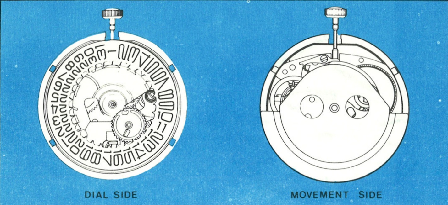
A Date on the Model 107
The Model 108 movement is a 13 ligne self-wind movement featuring the Timex “V-Conic” bearing system, two plate design and a fast change system for setting the date. The Model 108 contains a planetary gear self-winding system. The routine movement of the wrist of a normally active person is sufficient to keep the watch running without manual winding.
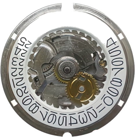
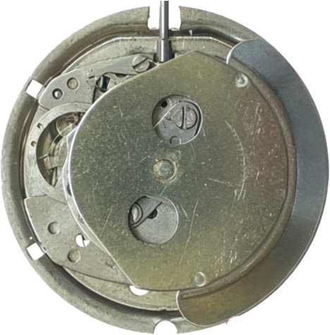
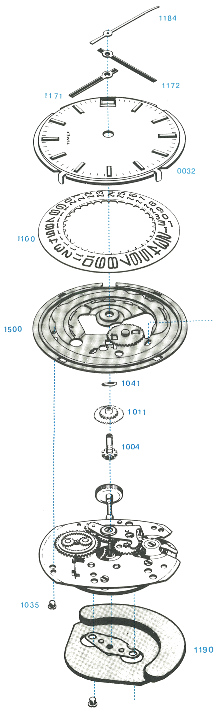
Exploded View
Everything below the numbered parts is the basic Model 104 movement.
Disassembly for Cleaning
Freeing the Rotor Assembly
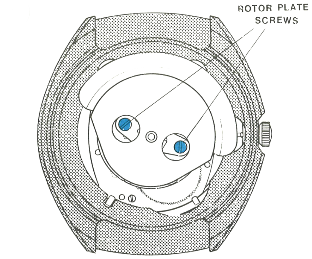
Remove the case back. Loosen and remove the two rotor plate screws.
Lift the rotor assembly slightly to free the dowels.
Sliding It Out
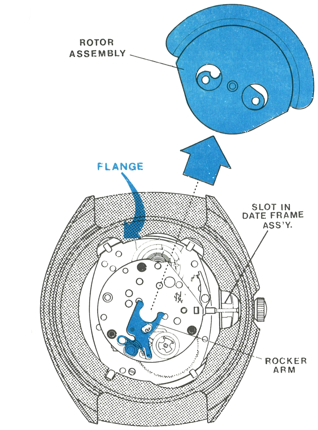
The rocker arm fits between the rotor frame and the rotor assembly. Position the rotor weight as shown and slide the assembly along the movement plate, toward the balance wheel, until it is free of the rocker arm, then lift the assembly out of the case.
Releasing the Crown and Stem
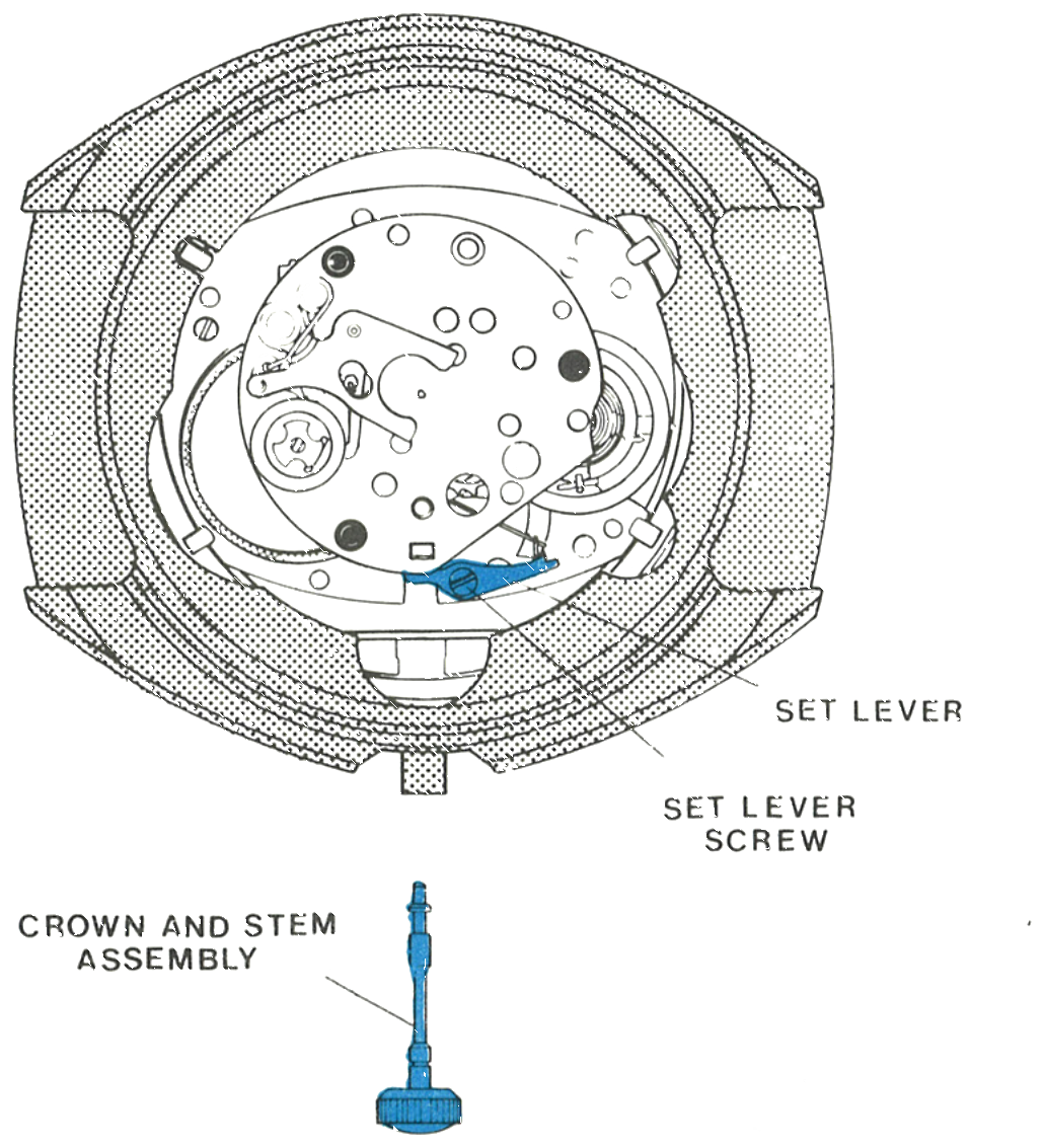
Loosen the set lever screw and raise the lever sufficiently to release the stem, then pull the crown and stem assembly free of the movement and the case.
Out of the Case
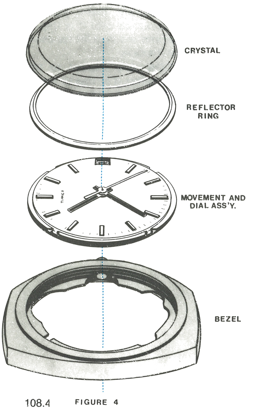
Where there is no retaining ring, turn the assembly over and remove the crystal using a crystal remover. The reflector ring and the movement and dial assembly can then be removed through the front of the bezel.
The Dial Tabs
Remove all hands. Turn the assembly over and bend the four dial tabs sufficiently to free the dial from the dial rest and the movement.
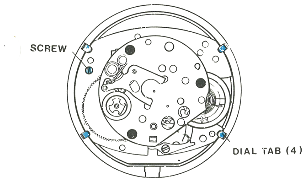
Off the Date Frame
Hold the dial in place and turn the assembly over so the dial is up. Carefully lift the dial off the assembly, noting the position of the parts underneath, then lift off the date ring and the date detent spring.
Replace the crown and stem assembly in the movement and tighten the set lever screw to assure engagement. Release the mainspring power slowly by holding the crown in the fingers of one hand while the click is held out of engagement with the ratchet wheel, through the hole in the date frame assembly.
Turn the assembly over, date frame down, and remove the screw securing the date frame assembly. Turn the assembly over again and lift off the date frame assembly and the ratchet wheel.
Remove the hour wheel washer (A), hour wheel assembly (B) and cannon pinion assembly (C) from the movement.
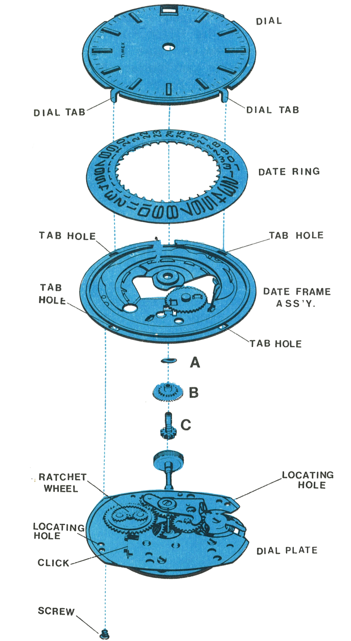
Cleaning
With the above parts removed, the basic movement of the Model 108 may be cleaned and relubricated as outlined for the Model 104 movement. Other metal parts may be cleaned in the same manner as the movement.
Reassembly
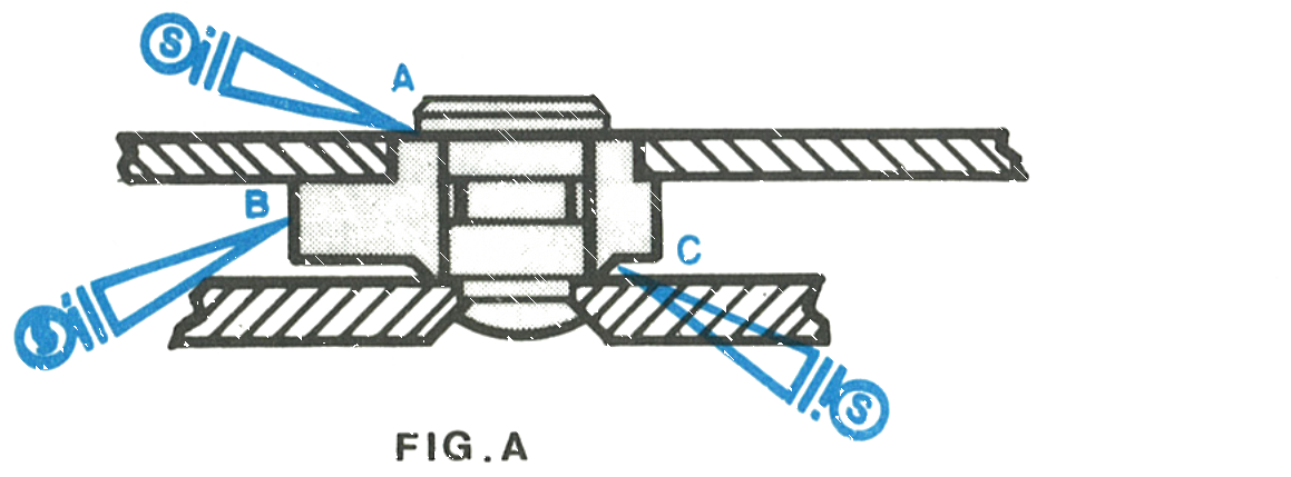
Greasing the Rotor Frame
Apply grease, Moebius special lubricant in the factory, to three points on the rotor frame assembly. Apply grease to the rotor cam at surface A, force grease beneath the rotor staff head at B and to the underside of the rotor cam at C.
Oiling the Slip Tail
Assemble the ratchet wheel and date frame and secure with the screw. Rotate the crown until the mainspring and slip tail are positioned as shown, then apply a drop of spreading type oil, Woods AAAA in the factory, in the space between the mainspring and the inside diameter of the barrel, or between the slip tail and the barrel, through the opening in the date frame.
Rotate the crown so the mainspring and slip tail make two complete revolutions within the barrel to distribute the oil properly. Release the mainspring power slowly, then remove the screw, date frame and ratchet wheel.
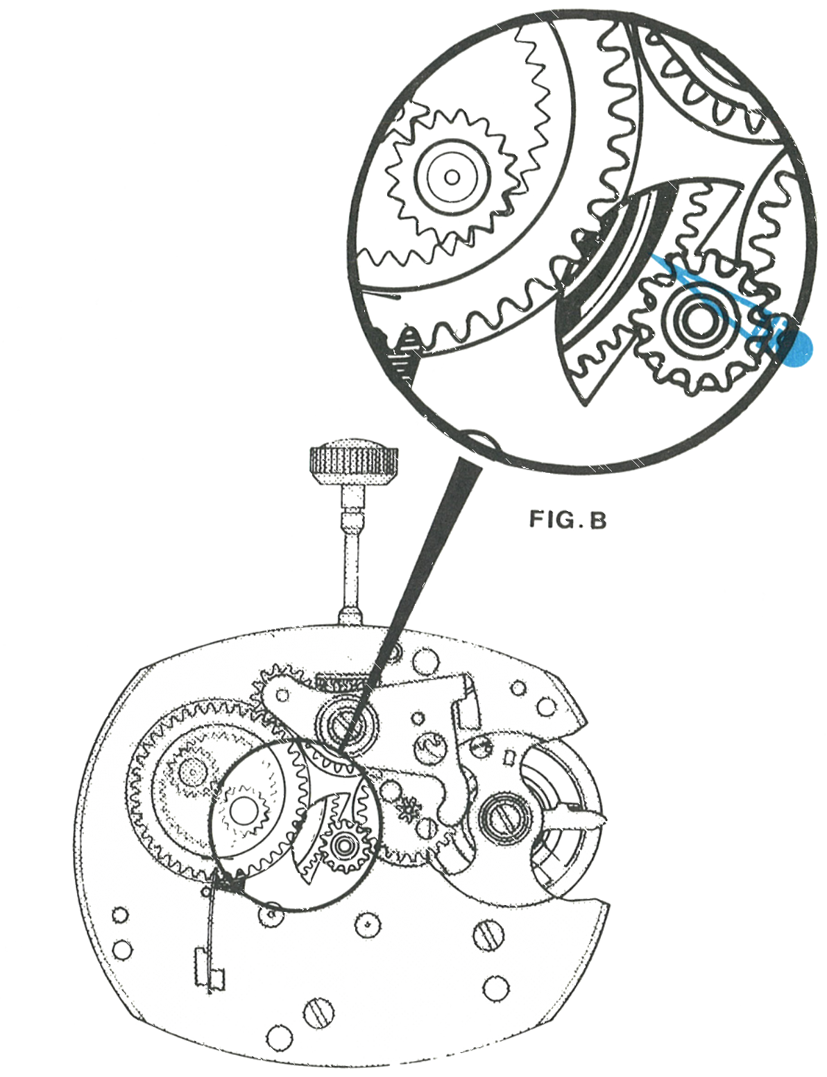
The Main Arbor and Ratchet Wheel
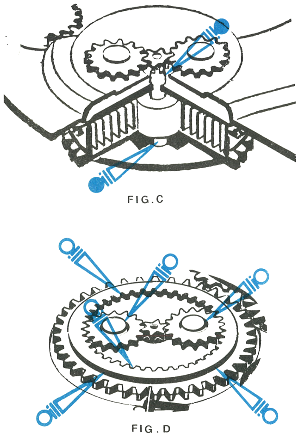
Place spreading type watch oil on the main arbor flat on one side, permitting oil to contact the root of the planet wind pinion teeth. From this point drag the oiler over the top of the planet wind pinion down to the main arbor flat on the opposite side, then apply spreading type oil to the bearing surface between the barrel hub and the movement plate.
Apply non-spreading type oil, Moebius Synt-A-Lube in the factory, to six points on the ratchet wheel and planet pinion assembly.
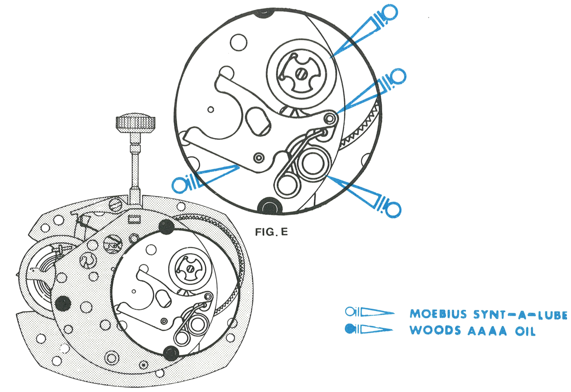
The Rocker Arm and Winding Ratchet Wheel
Apply non-spreading type oil to four points on the rocker arm assembly and winding ratchet wheel.
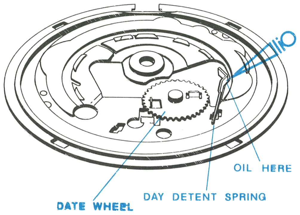
The Date Detent Spring
Insert the date detent spring into the date frame assembly as shown, then lubricate its bearing face with a thin film of non-spreading watch oil where shown.
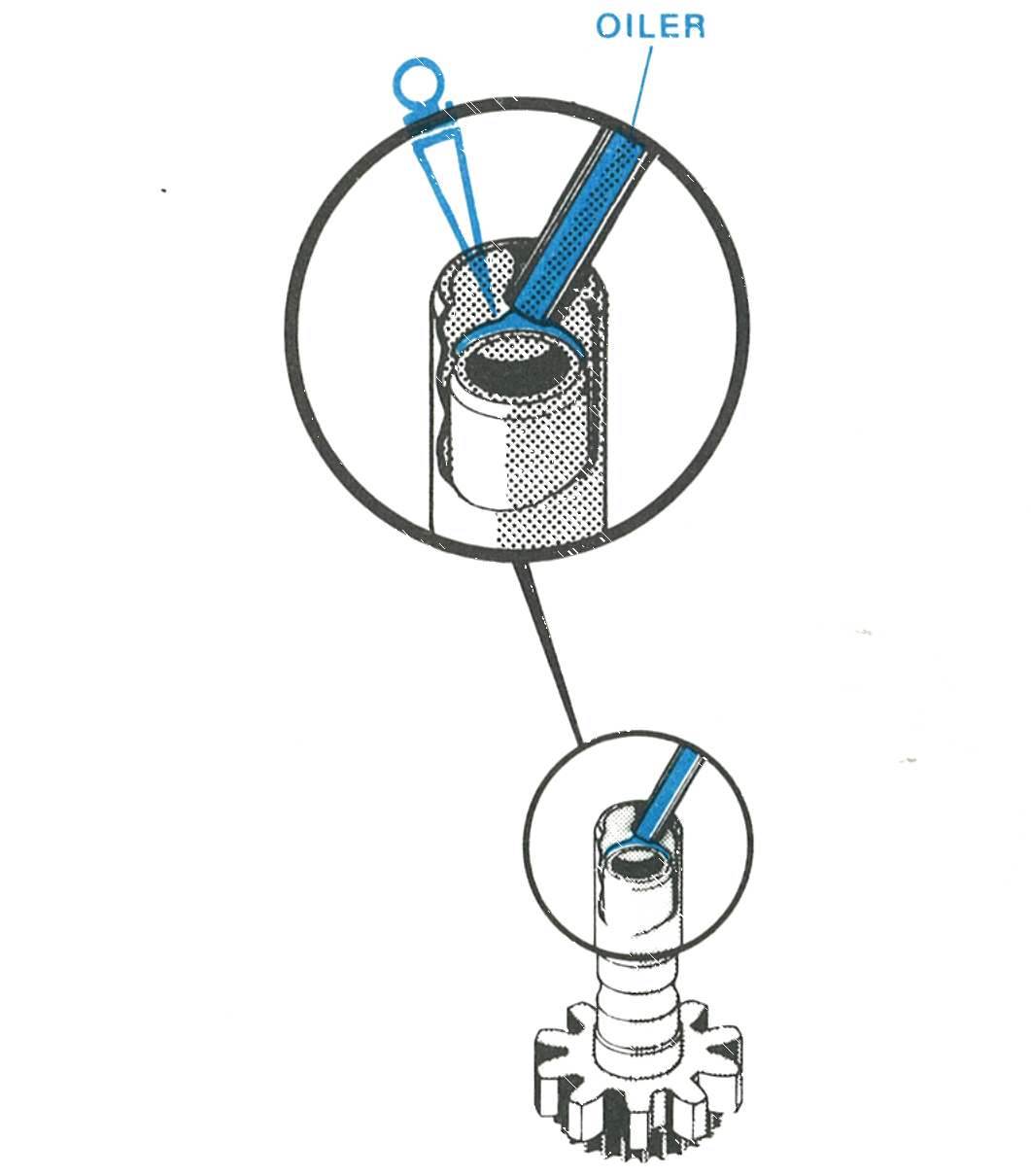
The Cannon Pinion
Apply non-spreading watch oil to the end of the cannon pinion.
Replace the parts on the movement in this order: cannon pinion assembly, hour wheel assembly, hour wheel washer, then the ratchet wheel, making sure it is seated and properly engaged with the click and the rocking bar assembly. Orient the date frame assembly with the slot at the stem and seat the bosses in the holes, turn the assembly over so the date frame is down, then insert and tighten the screw.
Dropping In the Date Ring
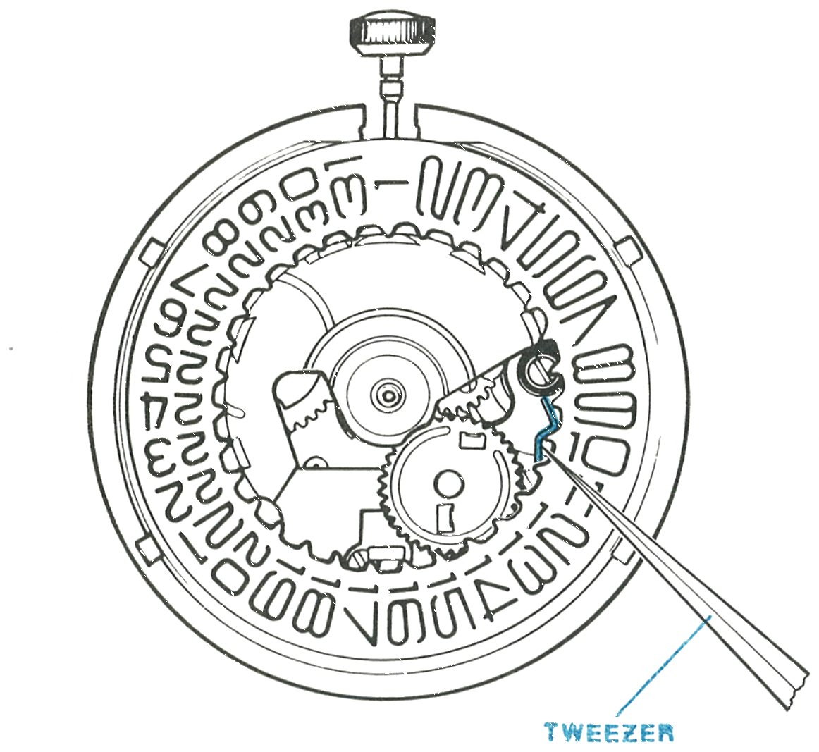
Position the date ring centrally on the date frame assembly. With a fine tweezer, deflect the date detent spring inward until the date ring drops into place.
Orient the dial with the window toward the crown and stem assembly and insert the dial tabs through the holes in the date frame assembly. Hold the dial in position on the movement, turn the assembly over and bend the tabs firmly over the edge of the dial plate. Pull the crown and stem out and rotate to turn the hands clockwise until the date changes with a snap, stop turning, and assemble the hands at the 12 o’clock position.
Checking the Change
Turn the crown so the hands rotate clockwise until the date advances one position. This should occur about midnight.
Rotate the hands counterclockwise to 9, then clockwise until the date advances again.
Rotate the hands clockwise through 24 hours and the date should advance one position.