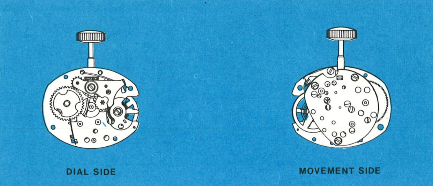
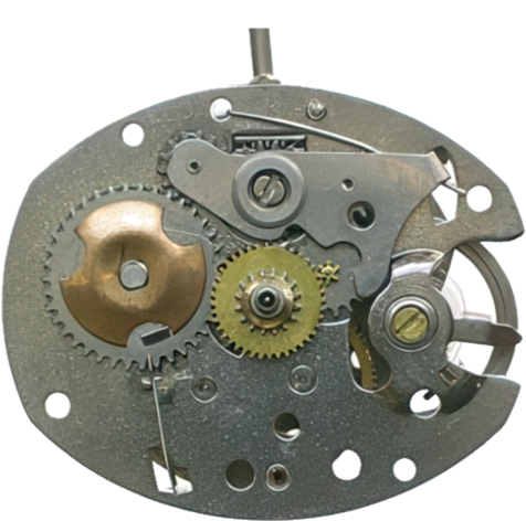
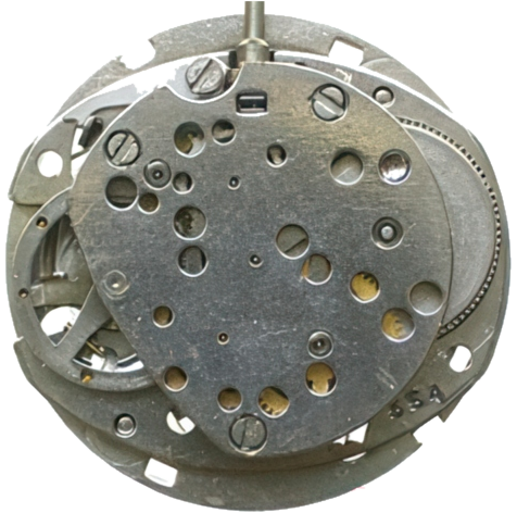
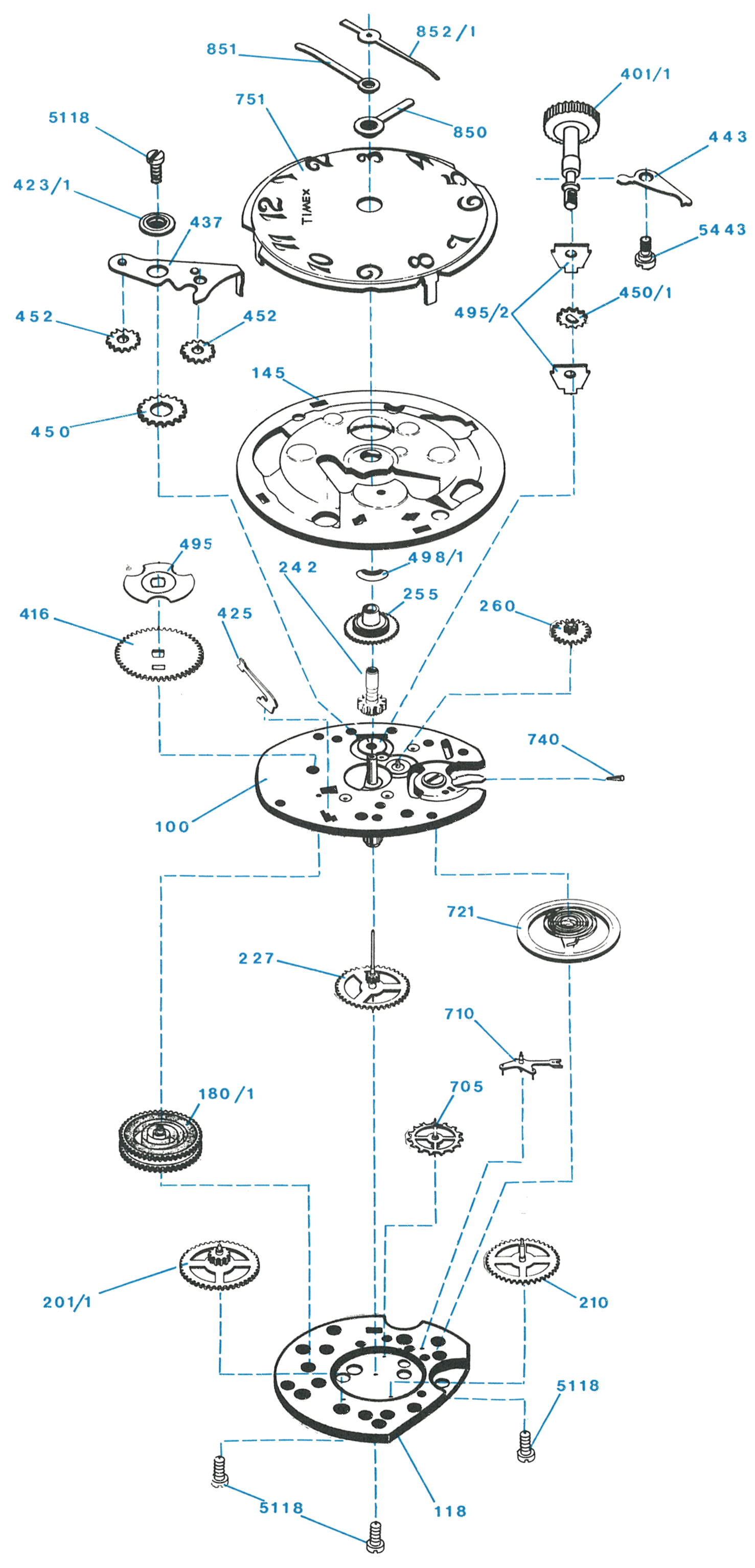
An 8 x 9½ ligne V-Conic two-plate movement. Similar to the Model 78 and Model 80, but with a simple click spring in place of a click assembly, and its own minute wheel, cannon pinion and hour wheel assemblies.
Hand-woundV-ConicTwo PlateClick Spring
Factory Service Manual · Model 100 · Dial Side & Movement Side
Size8 x 9½ ligne
BearingsV-Conic
ConstructionTwo plate
ClickSimple click spring
Similar toModels 78 and 80
Dial fixingFour tabs, A and B, through a dial rest
ManualService Manual · Model 100
Size (mm)18 × 21.95 mm
Height4.90 mm
Jewels0
EscapementPin lever
Beat rate18,000 bph
Power reserve41 h
Size in mm, height, jewels, escapement, beat rate and power reserve: ranfft.org
A Small V-Conic
The Timex 100 is an 8 x 9½ ligne movement featuring “V-conic” balance bearings and two plate design, similar to the Timex Model 78 and Model 80 movements.
Telling it apart: The easily noted difference is the use of a simple click spring on the Model 100 instead of a click assembly. Its minute wheel, cannon pinion and hour wheel assemblies also differ from the 78 and 80.
The Timex code number appears on the edge of the dial. The code number shows the catalog number, movement number and year of manufacture for the watch.
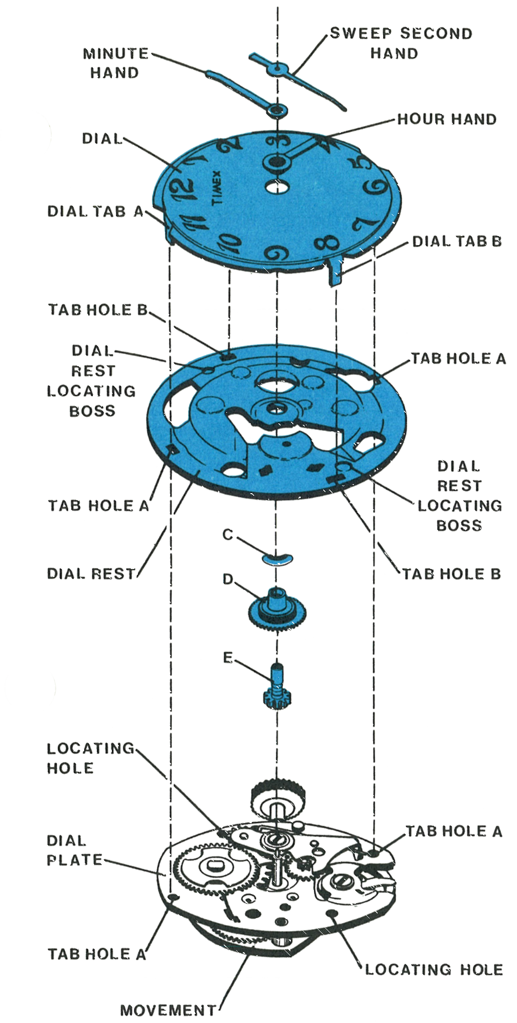
Straighten the two dial tabs marked A so they will pass through the holes. Hold the dial in place and straighten the dial tabs marked B slightly to permit the dial to come free of the movement. Turn the assembly over and lift off the dial.
Remove the hour wheel washer, hour wheel assembly and cannon pinion assembly, marked C, D and E respectively.
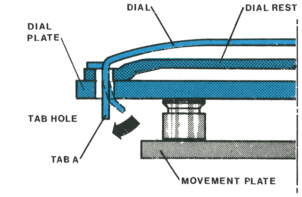
Fig. 100.3 · Dial & dial rest
2 · The Dial Rest
Cross section through the dial, dial rest, tab A and the dial plate.
Fig. 100.3 · Dial rest
3 · Removing the Balance Wheel
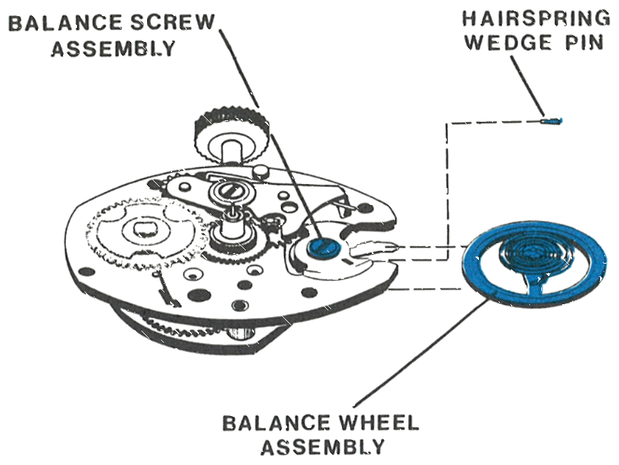
Remove the hairspring wedge pin, being careful not to distort either the pin or the hairspring.
Rotate the balance wheel carefully, turning the wheel and not touching the hairspring, until the hairspring tail is free of the hairspring bracket and the regulator.
Loosen the balance screw assembly counterclockwise until the end of the balance staff is sufficiently free of the “V-conic” bearing.
Carefully lift the balance wheel assembly out.
Caution: Only minimum downward pressure must be applied with the screwdriver. Excessive pressure can seriously damage the balance staff points.
Fig. 100.4 · Balance wheel
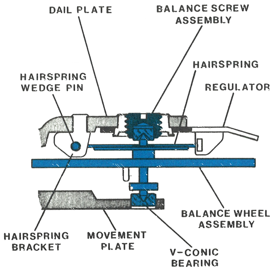
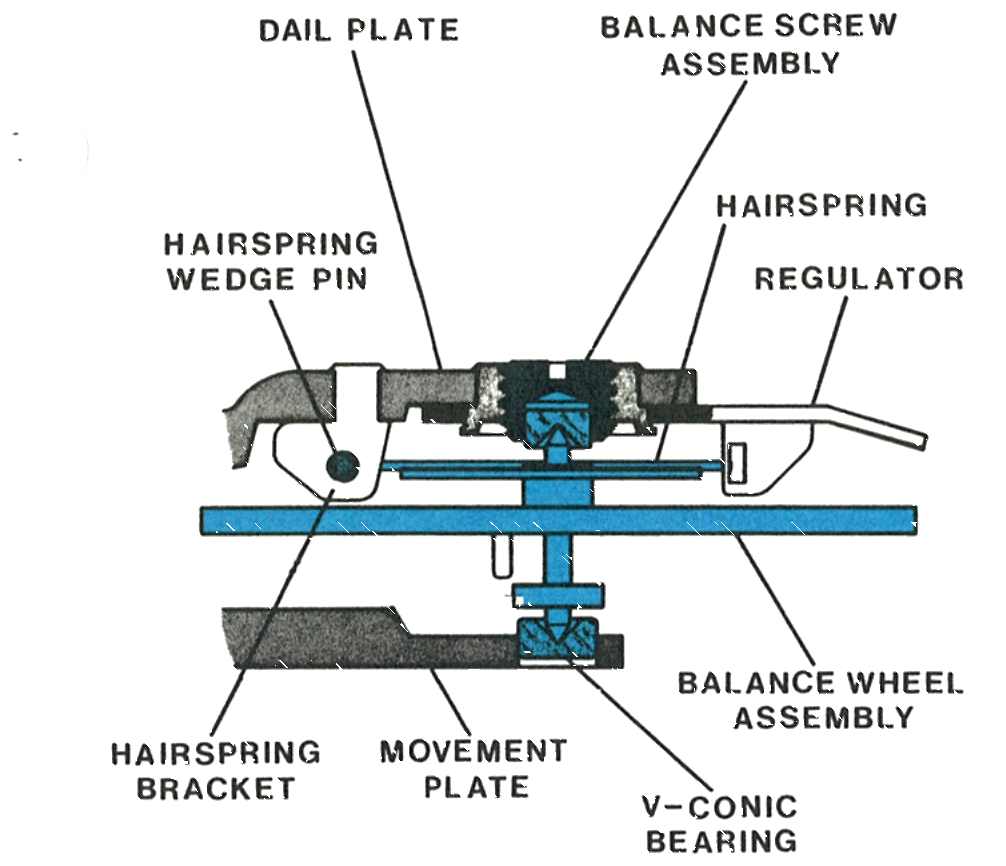
4 · The V-Conic Bearing
Cross section through the balance, showing the V-conic bearing in the balance screw assembly on the dial plate.
Fig. 100.4 · V-conic bearing
Cleaning
The movement, with only the balance wheel assembly and loose parts removed, can be cleaned satisfactorily in standard watch cleaning machines including ultrasonic baths. The movement should be placed in the machine with the dial plate down to insure proper drainage of the fluid from the mainspring barrel. The movement must be immersed in two sets of rinsing fluid; the final rinsing solution must be absolutely clean. After cleaning is completed, the movement must be thoroughly dried.
The balance wheel assembly must be cleaned separately in order to prevent damage to the balance staff points and the hairspring. Other metal parts may be cleaned as described above for the movement. Only standard watch cleaning solutions should be used.
Lubrication
The Model 100 should be lubricated using only high grade watch lubricants. The mainspring is permanently lubricated with a dry film lubricant which is not affected by normal watch cleaning solutions, therefore the mainspring requires no lubrication.
Spreading type watch oil, Woods AAAA in the factory, goes at two points at the side of the main arbor having the greater gap between the ratchet wheel washer and the main arbor. Also put spreading type oil on the main arbor on the movement plate side, and on the sweep second staff where it passes through the plate.
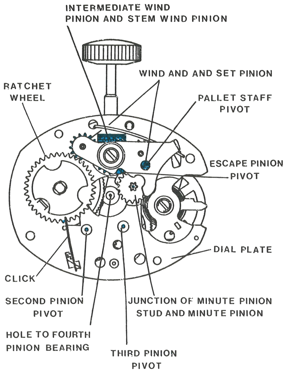
1 · Oil Points, Front View
The intermediate wind pinion and stem wind pinion, wind and set pinion, ratchet wheel, pallet staff pivot, escape pinion pivot, second and third pinion pivots, the click, the hole to the fourth pinion bearing, and the junction of the minute pinion stud and minute pinion.
Fig. 100.6 · Figure A, front view
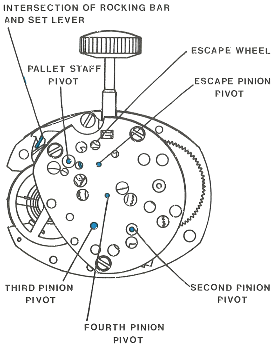
2 · Oil Points, Rear View
The intersection of the rocking bar and set lever, the escape wheel, the pallet staff pivot, escape pinion pivot and the third and fourth pinion pivots.
Fig. 100.6 · Figure B, rear view
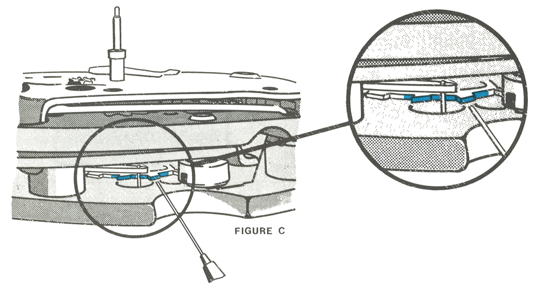
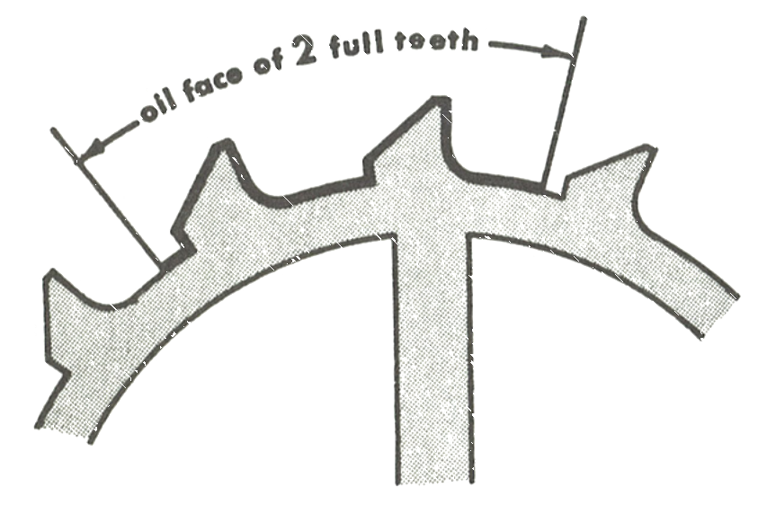
3 · The Escape Wheel Teeth
Apply the non-spreading watch oil to the full working surfaces of two escape wheel teeth. The manual shows the face of two full teeth.
Fig. 100.7 · Figure C
4 · The Escape Wheel in Place
The same two teeth shown on the movement, with the detail enlarged.
Fig. 100.7 · Figure D
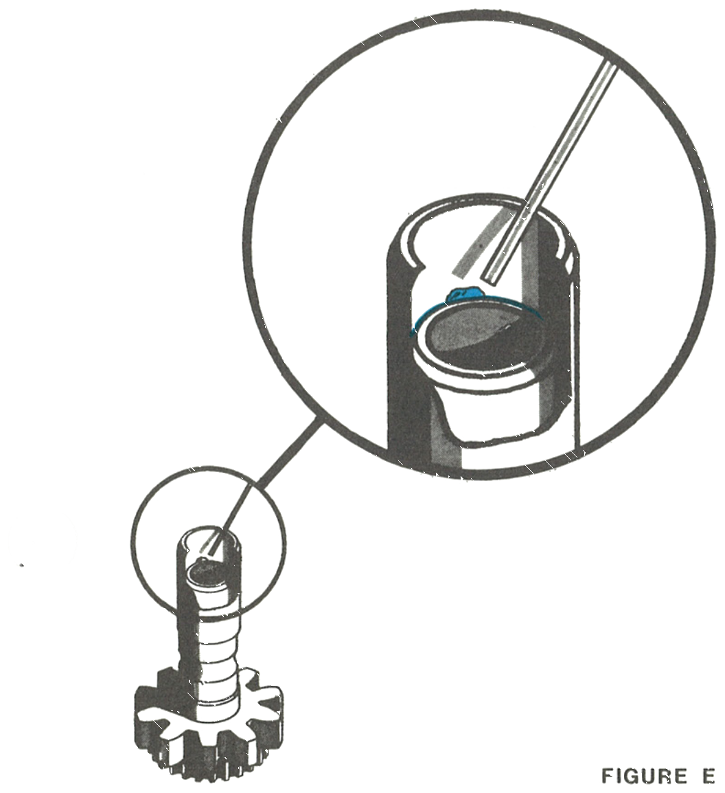
5 · The Cannon Pinion
Apply the non-spreading watch oil to the end of the cannon pinion assembly.
Fig. 100.7 · Figure E
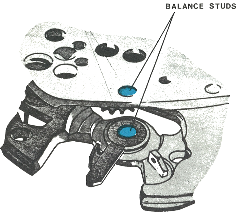
6 · The Balance Studs
Use non-spreading oil to fill both “V-conic” bearings ½ to ¾ deep.
Fig. 100.8 · Figure F
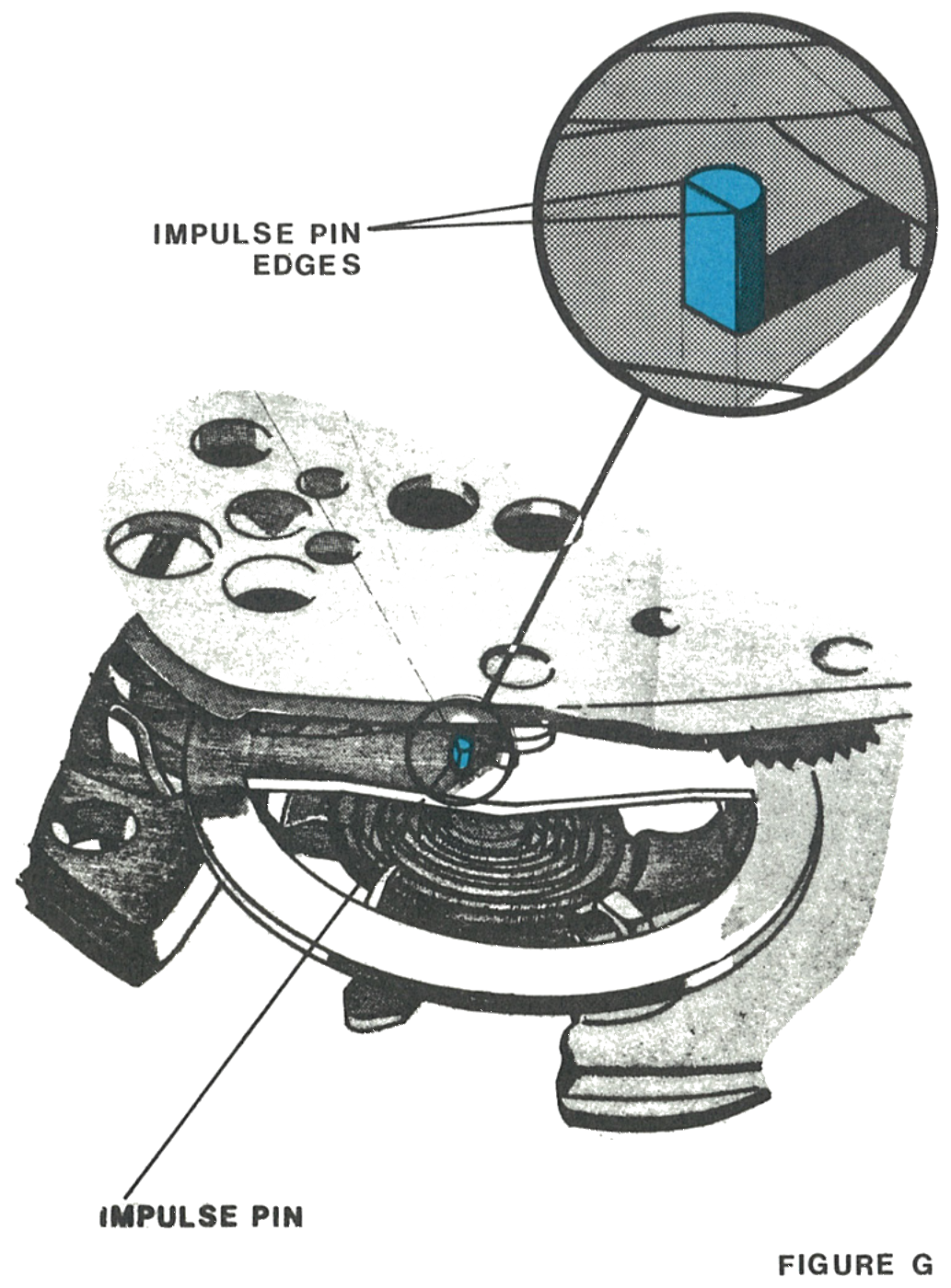
7 · The Impulse Pin
After the balance wheel assembly is replaced in the movement, apply non-spreading watch oil to both edges of the impulse pin where contact is made with the pallet lever fork.
Fig. 100.8 · Figure G
Reassembly
1 · Replacing the Balance Wheel
Loosen the balance screw assembly several turns.
Tilt the balance wheel assembly and carefully insert the dial side pivot, the hairspring end, and then the other pivot into the “V-conic” bearings. Tighten the balance screw assembly enough to hold the balance wheel assembly in place.
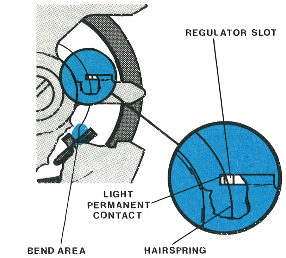
Insert the end of the hairspring into the slot in the regulator and then into the hole in the hairspring bracket, by rotating the balance wheel and guiding the end of the spring. Check that the impulse pin is in the slot of the pallet lever, then secure the hairspring in the bracket with the wedge pin.
Fig. 100.9 · Figure H
2 · The Regulator Slot
The hairspring in light permanent contact with the regulator slot, with the bend area shown enlarged.
Replace the parts on the movement in this order: cannon pinion assembly, hour wheel assembly, hour wheel washer, dial rest assembly, dial. Orient the dial rest on the movement so the two bosses are seated in the dial plate, then insert the dial tabs through the holes in the dial rest and into the dial plate. Hold the dial securely in place, carefully turn the assembly over and bend the A tabs and the B tabs under the dial plate to secure the dial firmly.
Fig. 100.9 · Figure J
Replace the parts in this order: cannon pinion assembly, hour wheel assembly, hour wheel washer, dial rest assembly, dial. Orient the dial rest so the two bosses seat in the dial plate, then insert the dial tabs through the holes in the dial rest and into the dial plate. Hold the dial securely, turn the assembly over and bend the A tabs and B tabs under the dial plate.
3 · Setting the Hands
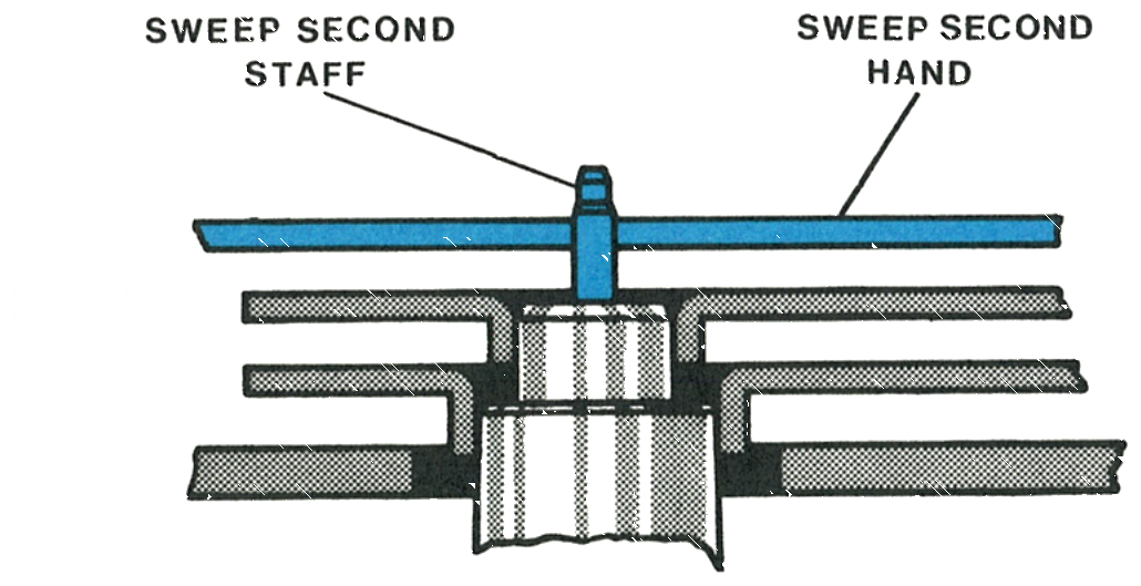
Turn the assembly over and assemble the hands. Be certain the sweep second hand is set below the chamfer on the top of the staff.
Fig. 100.9 · Figure K
Water resistant models: Special gasket lubrication is required. Apply silicon fluid, Dow Corning 200 Silicone Fluid 200 CS viscosity, to at least one half of the exposed gasket surface inside the crown assembly before assembling the crown and stem through the case.
This guide is based on the original Timex factory service manual for the Model 100 movement.